Wing skeleton antenna

A skeleton and antenna technology, applied in the field of wing skeleton antennas, can solve the problem that the aircraft cannot reduce the total weight of the airborne electronic load, achieve the effect of reducing the total weight and total occupied space, and improving functionality

Active Publication Date: 2022-07-08
CHINA ELECTRONIC TECH GRP CORP NO 38 RES INST
View PDF8 Cites 0 Cited by
  • Summary
  • Abstract
  • Description
  • Claims
  • Application Information

AI Technical Summary

Problems solved by technology

[0009] Aiming at the deficiencies of the prior art, the present invention provides a wing skeleton antenna, which solves the problem that the aircraft cannot reduce the total weight of the airborne electronic load

Method used


Image

  • Wing skeleton antenna
  • Wing skeleton antenna
  • Wing skeleton antenna

Examples


Embodiment 1

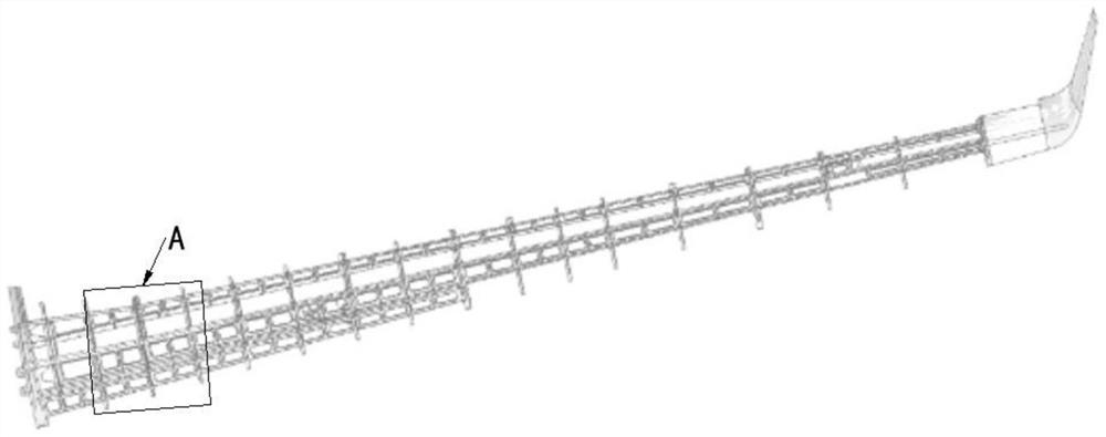
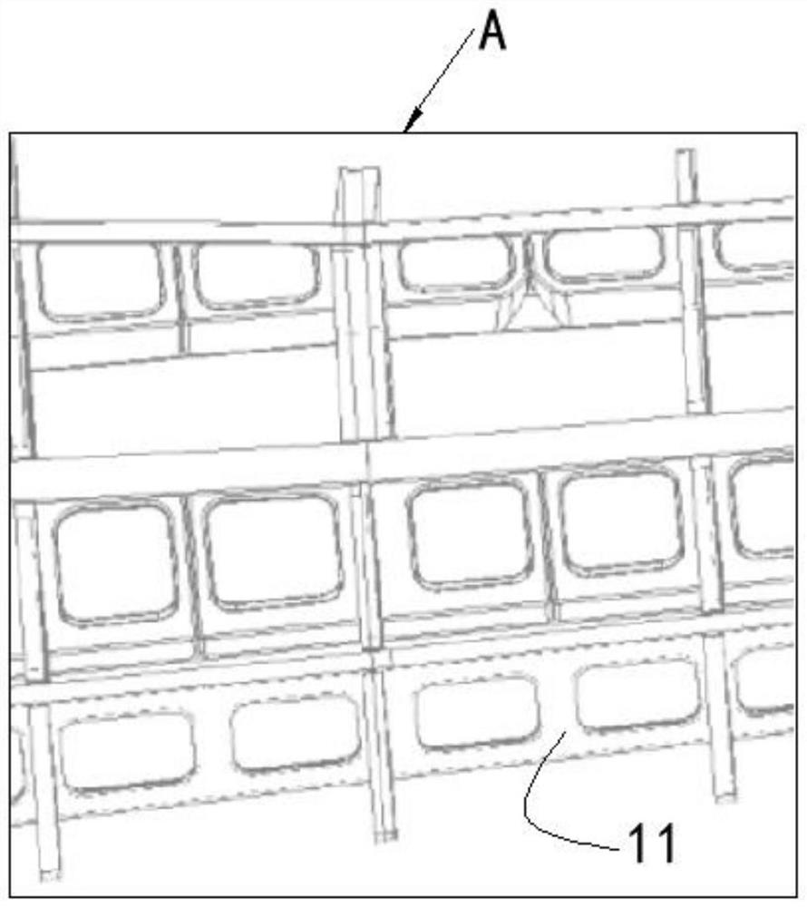
[0052] like Figures 1 to 3 As shown, the present invention provides a wing frame antenna, and the wing frame antenna includes: a plurality of frame modules 11;

[0053] The frame module 11 includes: a metal frame, a high-strength dielectric frame and a feeder;

[0054] The adjacent metal skeletons are mechanically connected by a high-strength dielectric skeleton, and on the basis of ensuring the structural strength and weight of the frame module 11 and the aerodynamic shape of the wing skeleton, electrical isolation between the metal skeletons is realized;

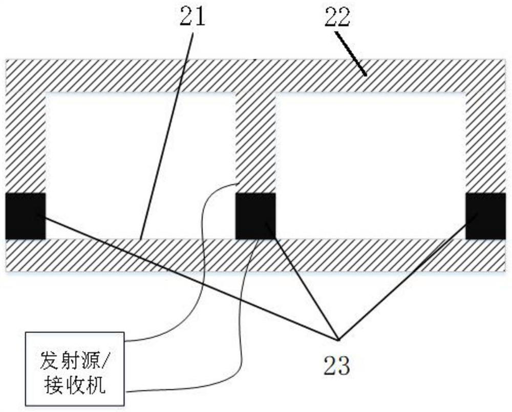
[0055] The metal frame is connected to the transmitting source and / or the receiver through the feeder, so as to realize the antenna function of the frame module 11 .

[0056] The wing frame itself realizes the antenna load with electromagnetic signal transmission and structural functions through the frame module 11, rather than moving the antenna load from the fuselage to the wing, which can effectively improve the functio...

Embodiment 2

[0067] like Figure 4 As shown, the frame module 11 includes: a reflector 31, two vibrator arms 32 and a second high-strength dielectric skeleton 33;

[0068] Adjacent reflectors 31 and vibrator arms 32 are connected by a second high-strength dielectric skeleton 33;

[0069] The two vibrator arms 32 are connected to the transmitting source and / or the receiver through the feeder, so as to realize the function of the dipole antenna of the frame module 11 .

[0070] The standing wave simulation results of the dipole antenna are as follows Figure 7 As shown, the dipole antenna can have a standing wave better than 2.6 in a working bandwidth of 0.5-2 GHz and 4:1 octave, and can achieve ultra-wideband characteristics.

[0071] The simulation results of the pattern of the dipole antenna are as follows Figure 8 As shown, the dipole antenna can achieve a downward main lobe beam within a working bandwidth of 0.5-2 GHz and 4:1 octave, which can meet the needs of the aircraft to commu...

Embodiment 3

[0073] like Figure 5 As shown, the frame module 11 includes: a third metal frame 41 and a third high-strength dielectric frame 42;

[0074] The third high-strength dielectric skeleton 42 divides the third metal skeleton 41 into metal arms of the folded dipole antenna, and both sides of the opening of the third metal skeleton 41 are connected to the transmitting source and / or the receiver through feeders to realize the frame Folded dipole antenna function of module 11.


PUM


Abstract

The invention provides a wing skeleton antenna, and relates to the technical field of antennas. The wing skeleton antenna comprises: a plurality of frame modules; the frame module comprises a metal framework, a high-strength medium framework and a feeder line; the adjacent metal frameworks are mechanically connected through the high-strength medium frameworks, and on the basis that the structural strength and weight of the frame module and the aerodynamic shape of the wing framework are guaranteed, electrical isolation between the metal frameworks is achieved. The metal framework is connected with a transmitting source and/or a receiver through a feeder line to realize an antenna function of the framework module; the wing skeleton realizes the antenna load with electromagnetic signal emission and structure functions through the frame module instead of moving the antenna load from the fuselage to the wing, so that the functionality of the wing skeleton can be effectively improved, and the total electronic load weight and the total occupied space of the aircraft are reduced.

Description

technical field [0001] The invention relates to the technical field of antennas, in particular to a wing frame antenna. Background technique [0002] With the rapid development of aircraft technology, reducing the weight of the electronic load on the aircraft and improving the flight time of the aircraft have increasingly become the focus of scholars and manufacturers in colleges and universities. The wing is an important part of the aircraft. Although the size of the wing is large in the unfolding direction, the internal space of the wing is small, and the metal wing skeleton structure is densely covered to ensure the structural strength required for the flight function. Underutilized in aircraft, the wings only provide aerodynamic flight. [0003] In recent years, various wing skin conformal antennas have been proposed. Such antennas typically have a low profile and can be conformally designed to fit the contour of the wing skin. The wings equipped with such wing skin a...

Claims


Application Information

Patent Timeline
Patent Type & Authority Applications(China)
IPC IPC(8): H01Q1/36H01Q1/44H01Q1/28H01Q1/50H01Q9/16H01Q19/02H01Q19/10B64C1/36B64C3/18
CPCH01Q1/36H01Q1/44H01Q1/50H01Q1/285H01Q9/16H01Q19/10H01Q19/02B64C1/36B64C3/18
Inventor 车邦军王泉金谋平张小林方佳张力维
Owner CHINA ELECTRONIC TECH GRP CORP NO 38 RES INST
Why Eureka
Try Eureka