Distance measuring device
A technology for distance measurement and time, which is applied in the directions of measuring devices, distance measurement, line-of-sight measurement, etc., and can solve problems such as changes in distance measurement results
- Summary
- Abstract
- Description
- Claims
- Application Information
AI Technical Summary
Problems solved by technology
Method used
Image

Examples
no. 1 approach
[0040] Below, with the attached Figure 1 The first embodiment of the present disclosure will now be described.
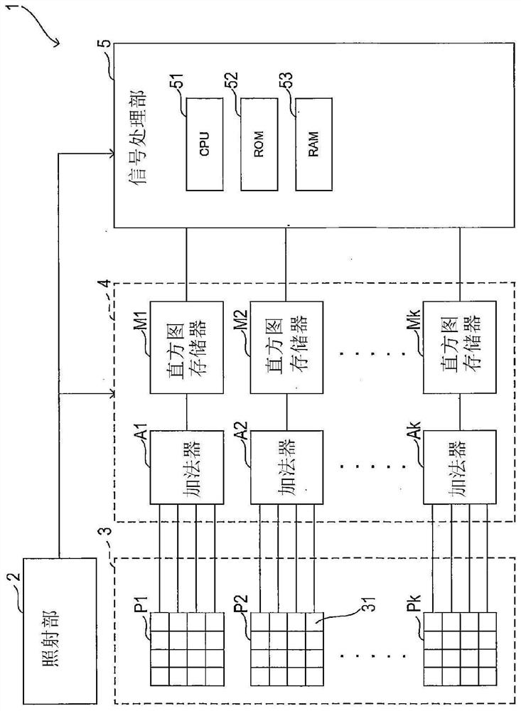
[0041] The distance measuring device 1 of the present embodiment is mounted on a vehicle, and measures distances to various objects existing around the vehicle.
[0042] like figure 1 As shown, the distance measuring device 1 includes an irradiation unit 2 , a light-receiving array unit 3 , a counting unit 4 , and a signal processing unit 5 .
[0043] The irradiation unit 2 repeatedly irradiates pulsed laser light (hereinafter, referred to as signal light) at predetermined intervals, and notifies the counting unit 4 and the signal processing unit 5 of the irradiation timing. Hereinafter, the period during which the laser light is irradiated will be referred to as a measurement period.
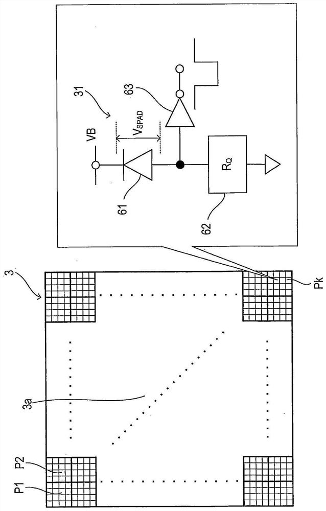
[0044] The light-receiving array section 3 includes a plurality of pixel units P1, P2, . . . , Pk. K is an integer of 2 or more. Each pixel unit Pi includes N photodetectors 31...
no. 2 approach
[0108] Below, with the attached Figure 1 The second embodiment of the present disclosure will now be described. In addition, in the second embodiment, different parts from the first embodiment will be described. The same reference numerals are attached to the same configuration.
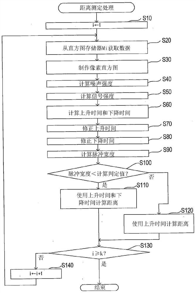
[0109] The distance measurement device 1 of the second embodiment differs from the first embodiment in that the distance measurement process is changed.
[0110] like Figure 11 As shown, the distance measurement process of the second embodiment differs from the first embodiment in that the process of S82 is executed instead of S80.
[0111] That is, when the process of S70 ends, the CPU 51 corrects the fall time Td in S82, and transfers to S90.
[0112] like Figure 12 As shown, if a photon is incident on the SPAD61, the SPAD61 breaks down and a current flows through the quenching resistor 62, and a voltage drop occurs in the quenching resistor 62, so the voltage across the SPAD61 is V SPAD T...
no. 3 approach
[0126] Below, with the attached Figure 1 A third embodiment of the present disclosure will now be described. In addition, in the third embodiment, different parts from the first embodiment will be described. The same reference numerals are attached to the same configuration.
[0127] The distance measuring device 1 of the third embodiment differs from the first embodiment in that the configuration of the distance measuring device 1 is changed and the distance measuring process is changed.
[0128] like Figure 15 As shown, the distance measuring device 1 of the third embodiment differs from the first embodiment in that a temperature sensor 7 is added.
[0129] The temperature sensor 7 detects the temperature of the light-receiving array unit 3 and outputs a temperature detection signal indicating the detection result to the signal processing unit 5 .
[0130] like Figure 16 As shown, the distance measurement process of the third embodiment differs from the first embodim...
PUM
 Abstract
Description
Claims
Application Information
 - R&D
- Intellectual Property
- Life Sciences
- Materials
- Tech Scout
- Unparalleled Data Quality
- Higher Quality Content
- 60% Fewer Hallucinations
Browse by: Latest US Patents, China's latest patents, Technical Efficacy Thesaurus, Application Domain, Technology Topic, Popular Technical Reports.
© 2025 PatSnap. All rights reserved.Legal|Privacy policy|Modern Slavery Act Transparency Statement|Sitemap|About US| Contact US: help@patsnap.com