Non-magnetic ultraviolet disinfection system capable of detecting magnetic field deviation of lamp tube

A technology of ultraviolet and lamp tubes, which is applied in the direction of measuring magnetic variables, general control systems, control/adjustment systems, etc., can solve the problems of excessive placement position deviation, damage to ultraviolet lamp tubes, and placement position deviation, etc., to achieve Avoid abnormal damage effects

Pending Publication Date: 2022-07-12
深圳瑞格泰科医疗科技有限公司
View PDF0 Cites 0 Cited by
  • Summary
  • Abstract
  • Description
  • Claims
  • Application Information

AI Technical Summary

Problems solved by technology

[0006] The purpose of the present invention is to provide a non-magnetic ultraviolet disinfection system that can detect the offset of the magnetic field of the lamp tube, so as to solve the problem that the existing ultraviolet lamp tube is inserted into the magnetic resonance cavity, and the placement position is offset, and the placement position is too large Cause damage to UV lamps or ballast problems

Method used


Image

  • Non-magnetic ultraviolet disinfection system capable of detecting magnetic field deviation of lamp tube
  • Non-magnetic ultraviolet disinfection system capable of detecting magnetic field deviation of lamp tube
  • Non-magnetic ultraviolet disinfection system capable of detecting magnetic field deviation of lamp tube

Examples


Embodiment Construction

[0037] The technical solutions in the embodiments of the present invention will be clearly and completely described below with reference to the accompanying drawings in the embodiments of the present invention. Obviously, the described embodiments are only a part of the embodiments of the present invention, but not all of the embodiments. Based on the embodiments of the present invention, all other embodiments obtained by those of ordinary skill in the art without creative efforts shall fall within the protection scope of the present invention.

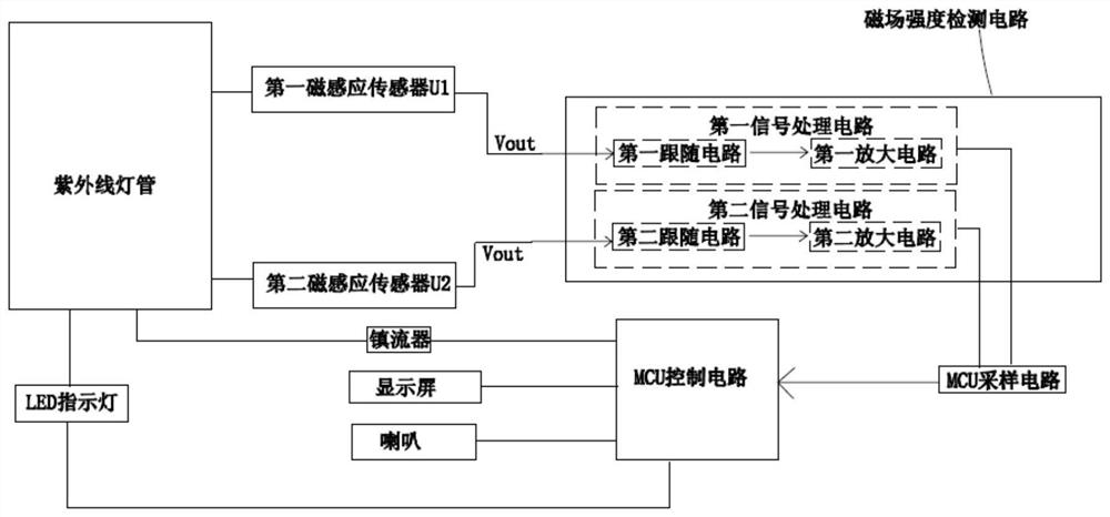
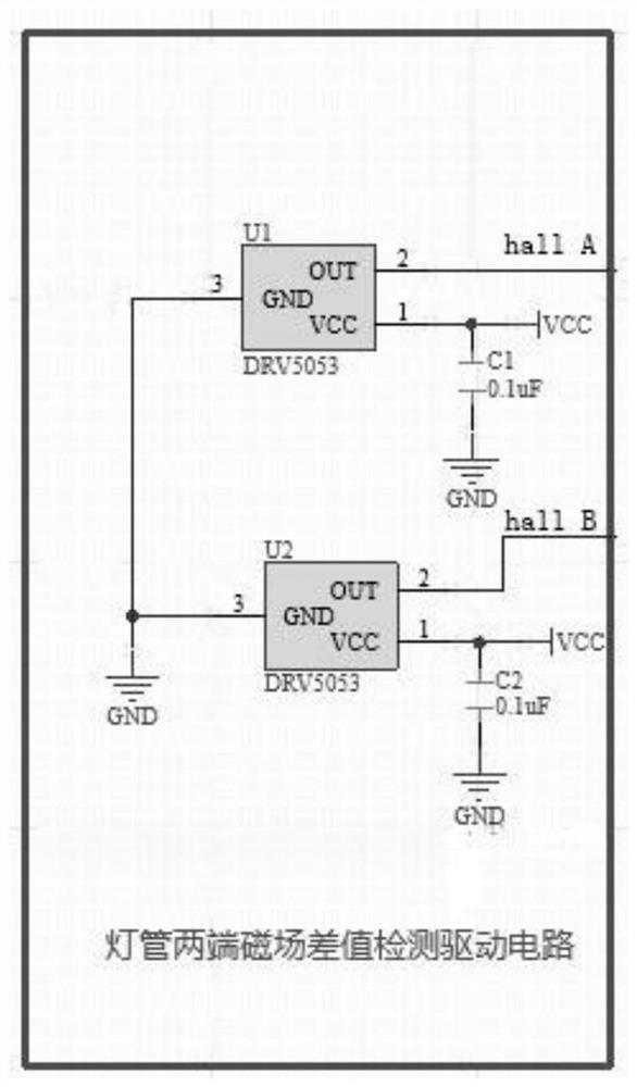
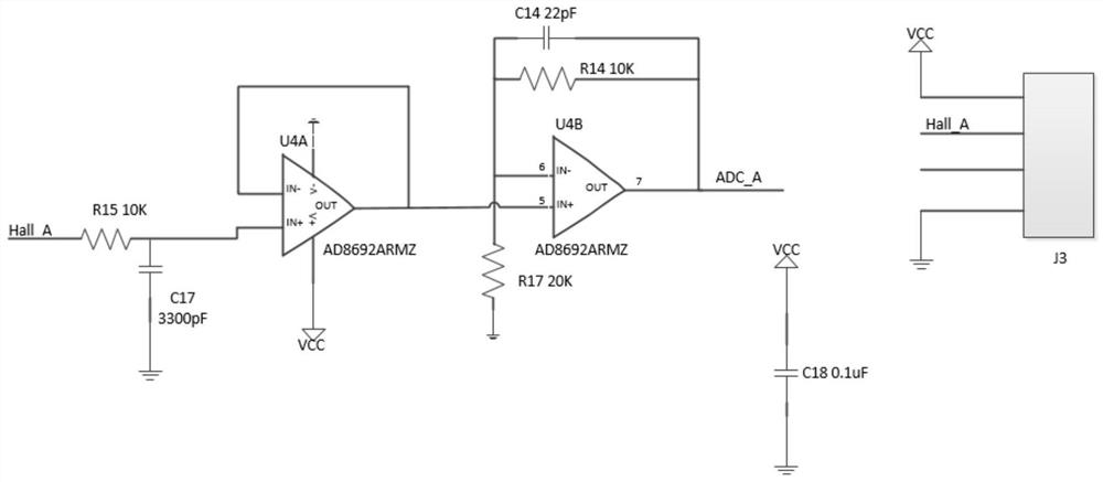
[0038] see Figure 1-7The invention provides a non-magnetic ultraviolet disinfection system that can detect the magnetic field deviation of the lamp tube, which includes: the ultraviolet lamp tube is used for disinfection, which is controlled by a MCU control circuit; the first and second magnetic induction sensors are used to detect the magnetic field strength, The first and second magnetic induction sensors are respectively placed a...


PUM

PropertyMeasurementUnit
electrical resistanceaaaaaaaaaa
capacitanceaaaaaaaaaa

Abstract

The invention discloses a non-magnetic ultraviolet disinfection system capable of detecting magnetic field deviation of a lamp tube. The non-magnetic ultraviolet disinfection system comprises an ultraviolet lamp tube, the first and second magnetic induction sensors are used for detecting magnetic field intensity and are respectively arranged at the head and tail ends of the ultraviolet lamp tube; the input end of the magnetic field intensity detection circuit is respectively connected with the output ends of the two magnetic induction sensors, and the magnetic field intensity detection circuit comprises a first signal processing circuit and a second signal processing circuit and is used for detecting and processing data of a magnetic field intensity difference value; an MCU sampling circuit; an MCU control circuit; a reminding module; and the MCU control circuit is used for presetting a magnetic field intensity difference threshold value and judging whether the current magnetic field intensity difference value exceeds the magnetic field intensity difference threshold value or not, and if the current magnetic field intensity difference value exceeds the magnetic field intensity difference threshold value, the MCU control circuit controls the ultraviolet lamp tube to be extinguished and triggers the reminding module. According to the invention, the ultraviolet lamp tube can be prevented from stretching into the magnetic resonance cavity, the placement position of the ultraviolet lamp tube is prevented from deviating too much, the ultraviolet lamp tube or a ballast is prevented from being damaged, and a user can use the magnetic resonance cavity conveniently and thoroughly disinfect the magnetic resonance cavity.

Description

technical field [0001] The invention relates to the technical field of ultraviolet disinfection, in particular to a non-magnetic ultraviolet disinfection system that can detect the magnetic field deviation of a lamp tube. Background technique [0002] At present, there are widely available ultraviolet disinfection vehicles with magnetism on the market, or magnetic resonance compatible non-magnetic disinfection vehicles with non-magnetic materials. [0003] The disadvantage is that the body of the magnetic ultraviolet disinfection car has strong magnetism and cannot be used in a magnetic resonance environment, while the non-magnetic disinfection car with non-magnetic material is used for the body. The circuit control board, ultraviolet lamps, etc. are still magnetic. This so-called non-magnetic disinfection vehicle can only be sterilized at a position 1 meter away from the magnetic resonance magnet. It cannot work near the magnet, and it cannot extend into the magnetic resona...

Claims


Application Information

Patent Timeline
Patent Type & Authority Applications(China)
IPC IPC(8): A61L2/10G01R33/07G05B19/042
CPCA61L2/10G01R33/07G05B19/0428G05B2219/2612Y02B20/40
Inventor 夏武兵
Owner 深圳瑞格泰科医疗科技有限公司
Why Eureka
Try Eureka