Plastic syringe needle separating device for hematology department
What is AI technical title?
AI technical title is built by PatSnap AI team. It summarizes the technical point description of the patent document.
A technology for separation devices and syringes, which can be used in the direction of needles, plastic recycling, and instruments introduced into the body, and can solve problems such as inconvenient classification
Pending Publication Date: 2022-07-12
刘徐安
View PDF0 Cites 0 Cited by
Summary
Abstract
Description
Claims
Application Information
AI Technical Summary
This helps you quickly interpret patents by identifying the three key elements:
Problems solved by technology
Method used
Benefits of technology
Problems solved by technology
[0005] In order to overcome the above disadvantages that when the syringe needle is separated by the hemostat or tweezers, it may be stabbed by the needle, causing infection and inconvenient manual classification after separation, the technical problem of the present invention is to provide a method for using The completed plastic injection molding machine needle can be automatically separated, and the plastic injection molding device that has separated the needle can be automatically unloaded, and the plastic syringe needle separation device for hematology does not need to manually sort the plastic syringes and needles
Method used
Image
Click on the blue label to locate the original text in one second.
Reading with bidirectional positioning of images and text.
Examples
Embodiment 1
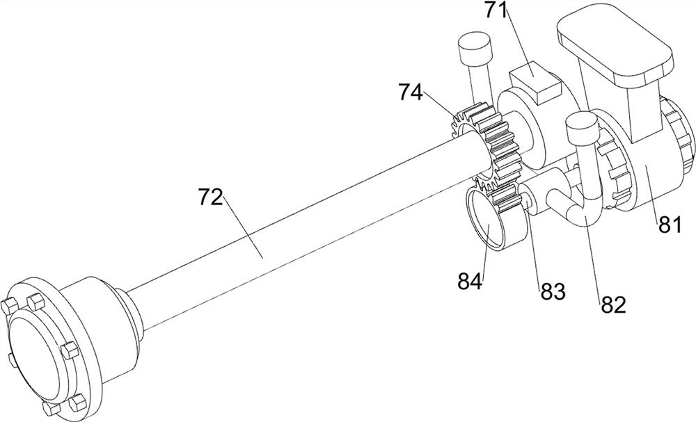
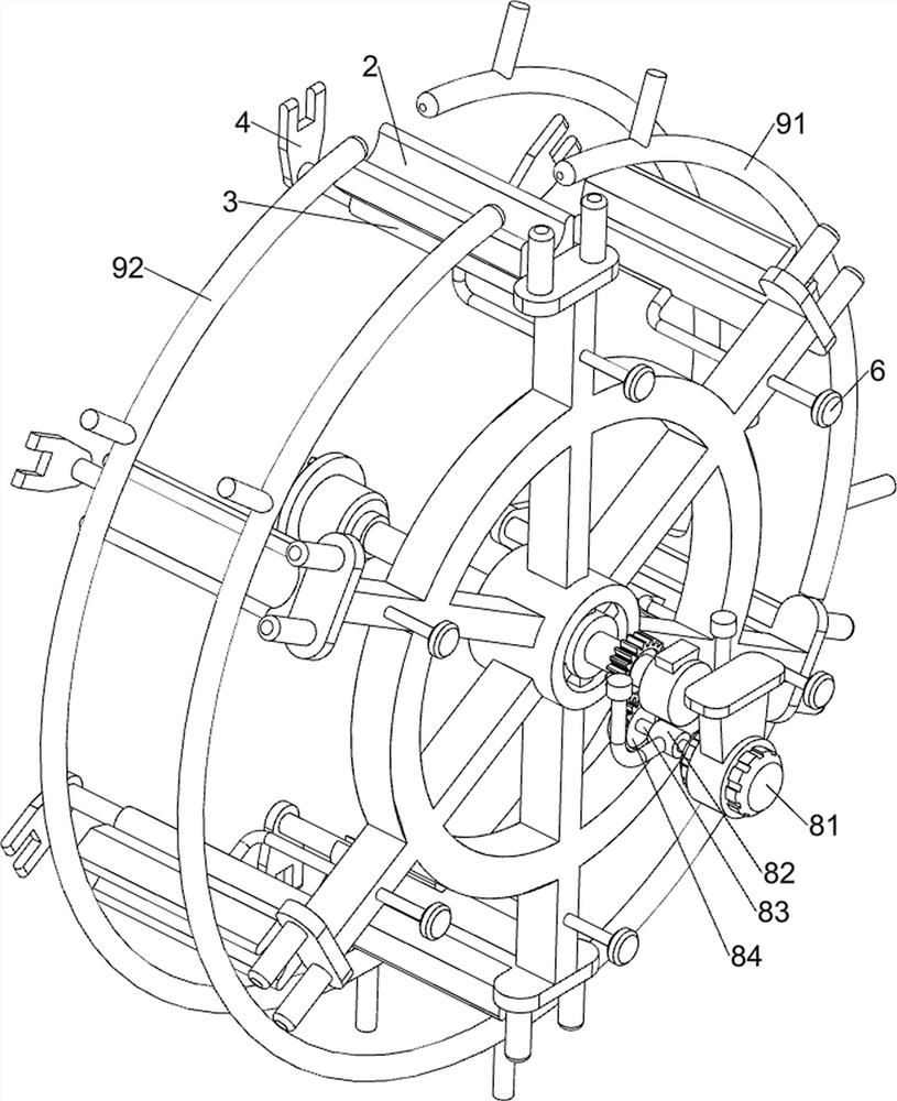
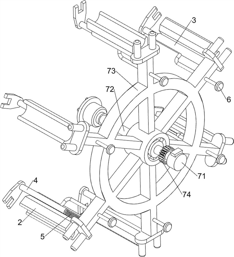
[0039] A plastic syringe needle separation device for use in hematology, such as figure 1 , figure 2 , image 3 , Figure 4 , Figure 5 , Image 6 , Figure 7 , Figure 8 , Figure 9 , Figure 10 , Figure 11 , Figure 12 and Figure 13 As shown, it includes a casing 1, a first bracket 1001, a second bracket 1002, a placing seat 2, a sliding cylinder 3, a push rod 4, a return spring 5, a contact rod 6, a rotating mechanism 7, a driving mechanism 8, a limiter For the mechanism 9 and the separation mechanism 10, the bottom of the casing 1 is provided with a first bracket 1001 symmetrically, the front side of the bottom of the casing 1 is provided with a second bracket 1002, the inner side of the casing 1 is provided with a rotating mechanism 7, and the components of the rotating mechanism 7 surround There are six placing seats 2 evenly, the inner side of the placing seats 2 are all provided with sliding cylinders 3, and the sliding cylinders 3 are all slidably provided...
Embodiment 2
[0046] On the basis of Example 1, as Figure 14 , Figure 15 , Figure 16 , Figure 17 and Figure 18 As shown, it also includes a blanking assembly 11, and the blanking assembly 11 includes a first guide rod 111, a second guide rod 112, a sliding frame 113, a second spring 114, a guide shaft 115, an ejector rod 116, and a third spring 117 and the wedge-shaped block 118, a first guide rod 111 is provided on the left rear part of the housing 1, a second guide rod 112 is provided on the left rear part of the housing 1, and the second guide rod 112 is located at the position of the first guide rod 111. Below, a sliding frame 113 is slidably connected between the first guide rod 111 and the second guide rod 112 , and a second spring 114 is connected between the sliding frame 113 and the first guide rod 111 and the second guide rod 112 . The springs 114 are respectively sleeved on the first guide rod 111 and the second guide rod 112 , and guide shafts 115 are provided on the pl...
PUM
Abstract
The invention relates to a needle separating device, in particular to a plastic syringe needle separating device for the hematology department. According to the plastic syringe needle separation device for the hematology department, used plastic injection syringe needles can be automatically separated, plastic injection syringes with separated needles can be automatically discharged, and plastic syringes and needles do not need to be manually classified. The plastic syringe needle separation device for the hematology department comprises a shell and first supports, and the first supports are symmetrically arranged at the bottom of the shell; the second support is arranged at the bottom of the shell; and the rotating mechanism is arranged on the inner side of the shell. According to the plastic injection molding device, the used plastic injection molding device needle head can be automatically separated, and the plastic injection molding device of which the needle head is separated can be automatically discharged.
Description
technical field [0001] The invention relates to a needle separation device, in particular to a plastic syringe needle separation device for hematology. Background technique [0002] Syringe is a medical tool used for suction and injection of liquid and gas. The syringe usually used in hematology department is made of plastic. It can suck and inject liquid and gas, and can also inject drugs through the skin and absorb various body fluids to diagnose and treat diseases. [0003] There will be a needle composed of a needle and a needle plug on the nipple in front of the syringe. According to the operating procedures, it is required to disassemble and separate the needle and needle tube after the syringe needle is used, and put the needle and needle tube in the sharps box and garbage collection bin respectively. . Now, the disassembly and separation operation of the needle and the barrel is usually performed by medical staff with hemostatic forceps or tweezers. There are two di...
Claims
Application Information
Patent Timeline
Application Date:The date an application was filed.
Publication Date:The date a patent or application was officially published.
First Publication Date:The earliest publication date of a patent with the same application number.
Issue Date:Publication date of the patent grant document.
PCT Entry Date:The Entry date of PCT National Phase.
Estimated Expiry Date:The statutory expiry date of a patent right according to the Patent Law, and it is the longest term of protection that the patent right can achieve without the termination of the patent right due to other reasons(Term extension factor has been taken into account ).
Invalid Date:Actual expiry date is based on effective date or publication date of legal transaction data of invalid patent.

