Auxiliary polishing device and polishing method for highway traffic guardrail
A technology for expressways and polishing devices, which is applied in the direction of grinding/polishing equipment, metal processing equipment, abrasive belt grinders, etc., and can solve the difficulty of adaptive adjustment of the deformation of the polishing surface, the fixed working area of polishing, and the inability to realize adaptive polishing operations and other problems, to achieve the effect of improving the polishing quality and scope of application, and improving the polishing area
- Summary
- Abstract
- Description
- Claims
- Application Information
AI Technical Summary
Problems solved by technology
Method used
Image
Examples
Embodiment 1
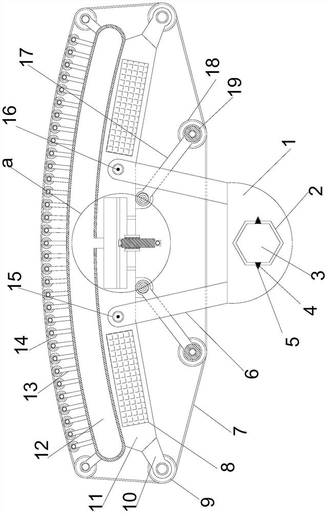
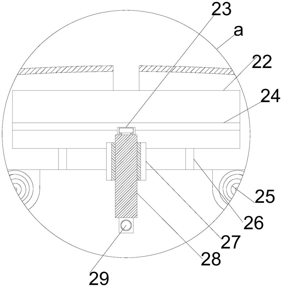
[0021] see figure 1 , figure 2 , Figure 4 , In the embodiment of the present invention, an auxiliary polishing device for a highway traffic guardrail includes a support installation column 3, and the support installation column 3 is provided with a plurality of combined polishing modules. Both the plate 1 and the support and installation column 3 are provided with a support and installation hole 2; the outer side of the support and installation column 3 is symmetrically provided with a guide conductive column 4, and the inner wall of the support installation hole 2 and the guide conductive column 4 are provided with a guide conductive groove 5; The support and installation plate 1 is provided with a work installation plate 11, and one side of the support and installation plate 1 is provided with a deformation mechanism, which is used to adapt to polishing operations on different surfaces; the interior of the support and installation plate 1 is symmetrically arranged with a ...
Embodiment 2
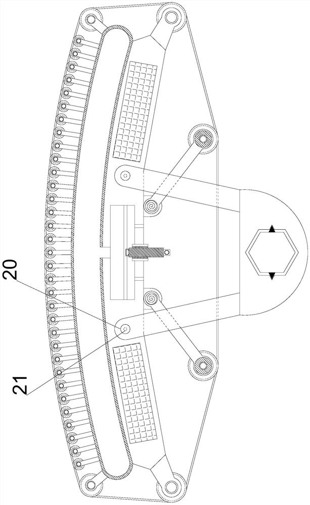
[0023] see figure 1 and figure 2 , In the embodiment of the present invention, the four corners of the side of the support installation plate 1 facing the operation installation plate 11 are protruded with fixed installation columns 6, and the outer ends of the fixed installation columns 6 are all fixed on the operation installation plate 11. The fixed mounting post 6 on one side of the mounting plate 11 is provided with a positioning mounting post 20 , and the fixed mounting post 6 and the positioning mounting post 20 on the other side of the operation mounting plate 11 are provided with positioning mounting holes 15 . The bottom is provided with a power supply protrusion 16, and the positioning mounting post 20 and the power supply protrusion 16 are provided with a power supply groove 21;
[0024] By supporting the mounting column 3 and the supporting mounting holes 2 and 2, the combined installation of several groups of combined polishing modules is realized, which is sui...
Embodiment 3
[0026] see figure 1 and figure 2 In the embodiment of the present invention, the deformation mechanism includes a deformation airbag 12 arranged on one side of the operation mounting plate 11, and a support roller 9 is symmetrically arranged on the outer side of the deformation airbag 12 through the mounting frame 10, and the outer side of the deformation airbag 12 between the support rollers 9 is uniform A number of displacement rollers 14 are provided, and the displacement rollers 14 are all fixed on the deformation airbag 12 by the displacement frame 13; The other side of the rotating mounting bracket 17 is symmetrically arranged with two rotating mounting brackets 17, one end of the rotating mounting bracket 17 is fixed on the operation mounting plate 11 through the reset rotating shaft 25, and the other end of the rotating mounting bracket 17 is provided with a driving motor 19. The driving motor 19 A driving drum 18 is provided through the rotating shaft, and a polishi...
PUM
 Abstract
Description
Claims
Application Information
 - R&D
- Intellectual Property
- Life Sciences
- Materials
- Tech Scout
- Unparalleled Data Quality
- Higher Quality Content
- 60% Fewer Hallucinations
Browse by: Latest US Patents, China's latest patents, Technical Efficacy Thesaurus, Application Domain, Technology Topic, Popular Technical Reports.
© 2025 PatSnap. All rights reserved.Legal|Privacy policy|Modern Slavery Act Transparency Statement|Sitemap|About US| Contact US: help@patsnap.com


