Heat pump water heater and method for controlling exhaust temperature of compressor of heat pump water heater

A temperature control method and compressor exhaust technology, applied in the field of heat exchange, can solve problems such as abnormal startup, abnormal startup of the compressor, and inability to start, and achieve the effects of improving stability, reducing exhaust temperature and flexible adjustment.

Pending Publication Date: 2022-07-12
ZHEJIANG ZHONGGUANG ELECTRIC CO LTD
View PDF0 Cites 0 Cited by
  • Summary
  • Abstract
  • Description
  • Claims
  • Application Information

AI Technical Summary

Problems solved by technology

[0003] In order to solve the problem in the prior art that when the ambient temperature is low and the water temperature in the unit is high, the exhaust temperature of the compressor is too high, resulting in abnormal startup of the compressor or even failure to start, the purpose of the present invention is to provide a heat pump The method for controlling the discharge temperature of the hot water machine and its compressor is to periodically adjust the flow rate of the refrigerant used for heat exchange in the unit by controlling the electronic expansion valve of the main circuit, and at the same time periodically adjust the discharge temperature of the compressor from The flow rate of the refrigerant sprayed out by the auxiliary circuit to cool down the compressor, thereby avoiding the problem that the unit cannot start and the startup is abnormal due to the high exhaust temperature when the compressor is started.

Method used


Image

  • Heat pump water heater and method for controlling exhaust temperature of compressor of heat pump water heater
  • Heat pump water heater and method for controlling exhaust temperature of compressor of heat pump water heater
  • Heat pump water heater and method for controlling exhaust temperature of compressor of heat pump water heater

Examples


Embodiment

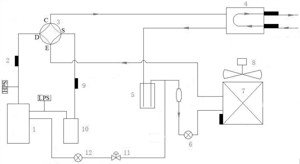
[0033] A control method of compressor discharge temperature, such as figure 1 As shown, it includes the main circuit for heat exchange and the auxiliary circuit for reducing the exhaust gas temperature. The refrigerant on the main circuit passes through the compressor 1, the four-way valve 3, the casing heat exchanger 4, the accumulator 5 and the fins in sequence. After the fin evaporator 7, it enters the gas-liquid separator 10 through the four-way valve 3 again, and then returns to the compressor 1. The pipeline connecting the accumulator 5 and the fin evaporator 7 is provided with a main circuit for controlling the flow of the refrigerant in the main circuit. One end of the auxiliary circuit is connected with the accumulator 5 and one end of the main circuit electronic expansion valve 6, the other end of the auxiliary circuit is communicated with the air inlet of the compressor 1, and the auxiliary circuit is installed with a liquid injection electronic expansion valve 12 an...


PUM


Abstract

The invention discloses a heat pump water heater and a method for controlling the exhaust temperature of a compressor of the heat pump water heater, and the method comprises the steps that a refrigerant on a main path sequentially passes through the compressor, a four-way valve, a double-pipe heat exchanger, a liquid storage device and a fin evaporator, then enters a gas-liquid separator through the four-way valve and then returns to the compressor; a main path electronic expansion valve for controlling the refrigerant flow of the main path is arranged on a pipeline for connecting the liquid storage device and the fin evaporator; the system further comprises an auxiliary path, one end of the auxiliary path is communicated with the liquid storage device and one end of the main path electronic expansion valve, the other end of the auxiliary path is communicated with an air inlet of the compressor, and a liquid spraying electronic expansion valve and a liquid spraying electromagnetic valve are installed on the auxiliary path. When the compressor is started under the conditions that the environment temperature is low and the water temperature in the unit is high, the main path electronic expansion valve and the liquid spraying electronic expansion valve are controlled to periodically adjust the flow of the refrigerant in the unit, and then the problems that when the compressor is started, due to the fact that the exhaust temperature is too high, the unit cannot be started, and starting is abnormal are avoided.

Description

technical field [0001] The invention relates to the field of heat exchange, in particular to a heat pump water heater and a method for controlling the exhaust temperature of its compressor. Background technique [0002] At present, most low-temperature heat pump water heaters on the market are used in an environment range of -25 to 45 °C, or even lower. The main purpose of the water heater is to provide users with hot water at a certain temperature. In a low temperature environment, when the water temperature is higher than 50 °C, the suction specific volume of the compressor increases, the suction volume decreases, the mass flow through the compressor decreases, and the cooling effect of the enameled wire of the motor inside the compressor is poor, especially in harsh environments. Under the working conditions of the compressor, as the water temperature increases, the compression ratio of the compressor increases, and the exhaust temperature also increases, and the exhaust ...

Claims


Application Information

Patent Timeline
Patent Type & Authority Applications(China)
IPC IPC(8): F25B29/00F25B13/00F25B41/20F25B49/02F24H4/02
CPCF25B29/003F25B13/00F25B41/20F25B49/02F24H4/02F25B2313/02741F25B2600/25F25B2400/19Y02B30/70
Inventor 游晓健凌拥军汪卫平杜君龙
Owner ZHEJIANG ZHONGGUANG ELECTRIC CO LTD
Why Eureka
Try Eureka