Dual-motor performance synchronous test device

A test device and dual-motor technology, applied in the direction of electromechanical devices, circuit devices, battery circuit devices, etc., can solve the problems of inability to test the performance of multiple motors and the serious energy consumption of multiple motor tests, so as to reduce the energy consumption of the test and reduce the Quantity, the effect of increasing the range of application

Pending Publication Date: 2022-07-12
HUNAN INSTITUTE OF ENGINEERING
View PDF2 Cites 0 Cited by
  • Summary
  • Abstract
  • Description
  • Claims
  • Application Information

AI Technical Summary

Problems solved by technology

[0007] The invention provides a dual-motor performance synchronous test device, which is used to solve the technical problem that the performance test of multiple motors cannot be carried out at the same time in the prior art, and the energy consumption of multiple motor tests is serious

Method used


Image

  • Dual-motor performance synchronous test device

Examples


Embodiment 1

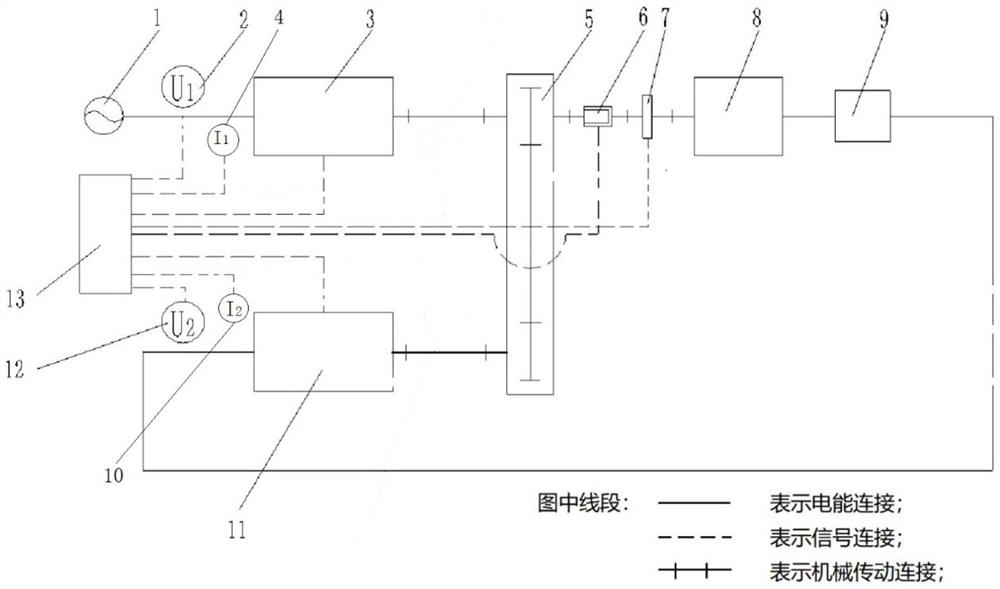
[0034] This implementation discloses a dual-motor performance synchronization test device, including: a power source 1, a power coupling device 5, a generator 8, an energy storage 9, and a controller 13;

[0035] The power output end of the power supply 1 is used to connect with the power input end of the first test motor 3 to provide power to the first test motor 3 for testing; the first power input end of the power coupling device 5 is used for Connected with the power output end of the first test motor 3, the second power input end of the power coupling device 5 is used to connect with the power output end of the second test motor 11, and the power output end of the power coupling device 5 be connected to the power input end of the generator 8 to couple the power of the first test motor 3 and the second test motor 11, and then transmit it to the generator 8 to drive the generator 8 to generate electricity;

[0036]The electrical energy input end of the accumulator 9 is conn...

Embodiment 2

[0040] The second embodiment is a preferred embodiment of the first embodiment. The difference between it and the first embodiment is that the specific structure of the dual-motor performance synchronization test device is expanded:

[0041] like figure 1 As shown, this embodiment discloses a dual-motor performance synchronization test device, including: a power supply 1, a power coupling device 5, a clutch 6, a generator 8, an energy storage 9, a controller 13, and a first voltage measuring device 2 , the second voltage measuring device 12, the first current measuring device 4, the second current measuring device 10, the torque and rotational speed measuring device 7; , the first power input end of the power coupling device 5 is used for connecting with the power output end of the first test motor 3 , and the second power input end of the power coupling device 5 is used for connecting with the power output end of the second test motor 11 The power output end is connected, an...


PUM


Abstract

The invention discloses a dual-motor performance synchronous test device, which comprises a power supply, a power coupling device, a generator, an energy storage device and a controller, the electric energy output end of the power supply is used for being connected with the electric energy input end of a first test motor, the first power input end of the power coupling device is used for being connected with the power output end of the first test motor, and the second power input end of the power coupling device is used for being connected with the power output end of a second test motor. The power output end of the power coupling device is connected with the power input end of the generator, the electric energy input end of the energy storage device is connected with the electric energy output end of the generator, and the electric energy output end of the energy storage device is used for being connected with the electric energy output end of a second test motor. And the signal end of the controller is used for being respectively connected with the signal ends of the first test motor and the second test motor. According to the invention, the number of loaders can be effectively reduced, performance tests can be carried out on two motors at the same time, the test efficiency is improved, and the test energy consumption can be reduced.

Description

technical field [0001] The invention relates to the field of motor performance testing, in particular to a dual motor performance synchronous testing device. Background technique [0002] Motors are widely used in travel gear and industrial equipment. In order to ensure that the working performance of the motor meets the design indicators, it is usually necessary to carry out experimental tests on the working performance of the motor during the product development stage. [0003] Patent No. 201811365667.6 discloses an electric vehicle motor performance test bench. In the test bench, upper and lower components are respectively set at a position corresponding to the positioning and installation of upper and lower fixtures, and the upper and lower components are connected by a transmission mechanism and run at the same time. Different sensors are respectively set in the lower components, so that the performance indicators of different types of motors can be measured through th...

Claims


Application Information

Patent Timeline
Patent Type & Authority Applications(China)
IPC IPC(8): G01R31/34G01L3/24G01D21/02H02J7/14H02K7/18
CPCG01R31/343G01L3/242G01D21/02H02K7/1807H02J7/14Y02T10/64
Inventor 黄中华谢雅
Owner HUNAN INSTITUTE OF ENGINEERING
Why Eureka
Try Eureka