
Fusion system of phase modifier and in-station energy storage of new energy power station

A technology of energy storage system and phase modulation, which is applied in energy storage, control/regulation system, wind power generation, etc., can solve the problems of current impact, difficulty in system voltage recovery, harmonic pollution of station power system, etc. performance, improve equipment reliability and energy storage system utilization, and ensure the effect of reliability

Pending Publication Date: 2022-07-12
NORTH CHINA ELECTRICAL POWER RES INST +1
View PDF0 Cites 0 Cited by
  • Summary
  • Abstract
  • Description
  • Claims
  • Application Information

AI Technical Summary

Problems solved by technology

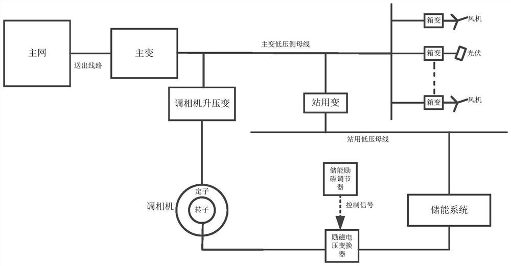
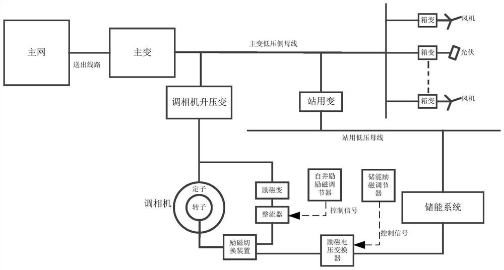
However, in the self-shunt static excitation mode adopted in the prior art, when the grid voltage drops, the primary side voltage of the excitation transformer also drops to a large extent, which is equivalent to that the power supply voltage of the excitation system is much lower than the normal level. It is still required to output a higher amplitude DC voltage, which indirectly puts forward higher requirements on the capacity and voltage level of the excitation system, increases the complexity of the system, and affects the dynamic performance of the excitation system, especially for new energy. In the weak power grid scenario of the station, it is impossible to give full play to the strong excitation effect of the condenser
In addition, because the excitation power comes from the machine end and is coupled with the condenser, it cannot provide 100% reliability support in essence. For example, when the excitation system fails, there is no corresponding backup excitation power supply.
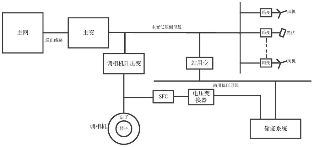
[0007] 2. When the SFC device (static start frequency converter) is used to start the condenser, the starting power comes from the station AC system. Using frequency conversion to start will cause harmful effects such as harmonic pollution and current impact on the station power system. In addition, when the system When the power is lost, the SFC will not be able to start the condenser, making it difficult to restore the system voltage

Method used


Image

  • Fusion system of phase modifier and in-station energy storage of new energy power station
  • Fusion system of phase modifier and in-station energy storage of new energy power station
  • Fusion system of phase modifier and in-station energy storage of new energy power station

Examples


Embodiment Construction

[0030] In order to make those skilled in the art better understand the solutions of the present application, the technical solutions in the embodiments of the present application will be clearly and completely described below with reference to the accompanying drawings in the embodiments of the present application. Obviously, the described embodiments are only The embodiments are part of the present application, but not all of the embodiments. Based on the embodiments in the present application, all other embodiments obtained by those of ordinary skill in the art without creative work shall fall within the protection scope of the present application.

[0031]It should be noted that the terms "first", "second" and the like in the description and claims of the present application and the above drawings are used to distinguish similar objects, and are not necessarily used to describe a specific sequence or sequence. It is to be understood that the data so used are interchangeable...


PUM


Abstract

The embodiment of the invention provides a new energy power station phase modifier and in-station energy storage fusion system which comprises a phase modifier and an energy storage system which are arranged in a new energy power station, and the fusion system comprises an energy storage independent excitation mode, an energy storage excitation and self-shunt excitation complementary mode, an energy storage independent starting mode and an energy storage standby starting mode. The phase modifier and the energy storage system in the new energy power station can be effectively fused, the reliability of the phase modifier equipment and the utilization rate of the energy storage system are improved, and the supporting effect of the phase modifier on the new energy power grid is fully exerted.

Description

technical field [0001] The present application relates to the field of new energy power systems, and in particular to a fusion system of a new energy power station controller and in-station energy storage. Background technique [0002] New energy power generation, such as the power system (wind power photovoltaic) with new energy as the main body, will become the main power source in the future power system. Insufficient short-circuit capacity and other problems, as a synchronous motor, the synchronous camera has the advantages of strong transient inactive power, large moment of inertia, and large short-circuit capacity. A proven solution. Due to the volatility and intermittency of wind and solar power, the frequency regulation and peak regulation performance of the power grid is poor, and energy storage has gradually become the standard for new wind farms and photovoltaic power plants, especially electrochemical energy storage. The camera and energy storage respectively s...

Claims


Application Information

Patent Timeline
Patent Type & Authority Applications(China)
IPC IPC(8): H02J3/46H02J3/28H02J3/38H02J3/01H02J3/50H02M3/24H02M7/04
CPCH02J3/466H02J3/28H02J3/381H02J3/01H02J3/50H02M3/24H02M7/04H02J2300/28H02J2300/22H02J2300/40Y02E70/30
Inventor 孙士涛卢毅雷雨宋鹏张杰
Owner NORTH CHINA ELECTRICAL POWER RES INST
Learn More