Spray head moisturizing system for digital textile printing equipment

A printing and equipment technology, applied in the field of nozzle moisturizing system for digital textile printing equipment, can solve the problems such as difficulty in controlling and guaranteeing moisturizing effect of moisturizing box, decreasing printing accuracy of printing nozzles, clogging of printing nozzles, etc. The effect of nozzle clogging

Active Publication Date: 2022-07-15
上海楚球智能科技有限公司
View PDF9 Cites 0 Cited by
  • Summary
  • Abstract
  • Description
  • Claims
  • Application Information

AI Technical Summary

Problems solved by technology

[0002] Digital textile printing technology is a high-tech product integrating machinery, computer and electronic information technology gradually formed with the continuous development of computer technology, which brings a new concept to the textile printing and dyeing industry. Digital printing machines are completed in use Finally,

Method used


Image

  • Spray head moisturizing system for digital textile printing equipment
  • Spray head moisturizing system for digital textile printing equipment
  • Spray head moisturizing system for digital textile printing equipment

Examples


Embodiment 1

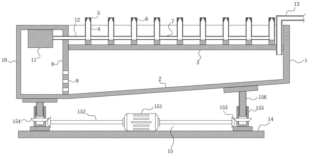
[0018] see figure 1 , The present invention provides a technical solution: a nozzle moisturizing system for digital textile printing equipment, comprising a water tank 1, a bottom plate 2 at the bottom end of the water tank 1 is inclined and arranged, a partition 8 is fixedly connected to the side of the water tank 1, and a side of the partition 8 is fixedly connected with The steam generating box 10, the bottom of the partition 8 is provided with a plurality of through holes 9 arranged at equal intervals, the through holes 9 communicate with the inner cavity of the water tank 1 and the inner cavity of the steam generating box 10, the bottom plate 2 is inclined to one side of the steam generating box 10, and the bottom plate 2. The angle formed with the horizontal line is an acute angle. A steam generator 11 is arranged in the steam generating box 10. The water in the water tank 1 flows into the steam generating box 10 through the through hole 9 due to gravity. The water in th...

Embodiment 2

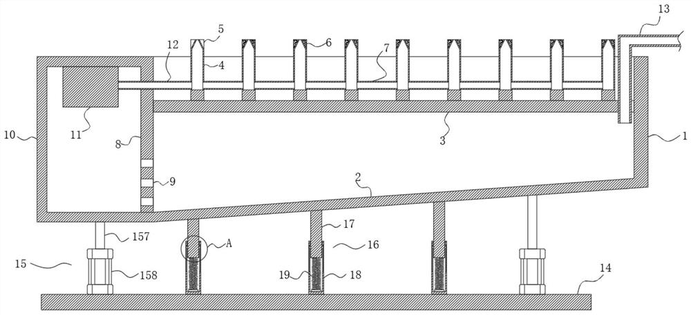
[0024] see Figure 2-3 , the present invention provides a solution different from the first embodiment: the lifting mechanism 15 includes a piston rod 157, a cylinder 158 and a telescopic support rod 16, the cylinder 158 is fixedly connected to the upper end of the mounting plate 14, there are at least two cylinders 158, and the cylinder 158 The upper end is provided with a piston rod 157, the upper end of the piston rod 157 is fixedly connected to the bottom end of the bottom plate 2, the cylinder 158 is connected to an external power supply and a control switch, after the cylinder 158 is activated, the piston rod 157 drives the water tank 1 to rise and fall;

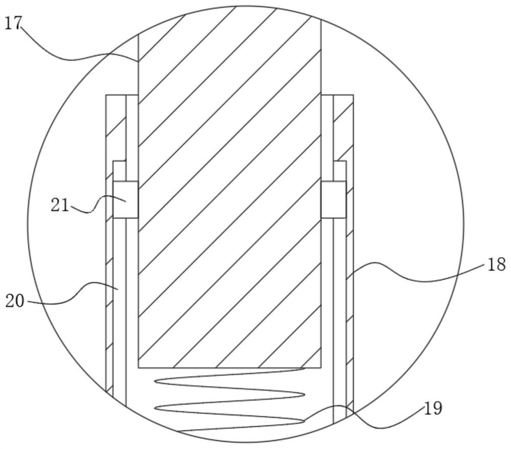
[0025] A telescopic support rod 16 is arranged between the bottom end of the bottom plate 2 and the mounting plate 14, and a plurality of telescopic support rods 16 are arranged at equal intervals. The telescopic support rod 16 includes a first support rod 17, a second support rod 18 and a spring 19. The upper end of t...


PUM


Abstract

The invention discloses a digital textile printing equipment nozzle moisturizing system which comprises a water tank, a partition plate is fixedly connected to the side face of the water tank, a steam generator is arranged in a steam generation box, a supporting plate is fixedly connected to the upper side of the water tank, a moisturizing pipe is fixedly connected to the supporting plate, and a steam pipe is arranged on the side face of the steam generator. A mounting plate is arranged at the bottom end of the water tank, and a lifting mechanism is arranged between the upper end of the mounting plate and the bottom end of the water tank. According to the spray head moisturizing system for the digital textile printing equipment, liquid in the water tank is converted into steam through the steam generator, the steam is conveyed into the moisturizing pipe through the steam pipe and the guide pipe to moisturize the spray head, the steam moisturizing means is mild and effective, and the phenomenon that the spray head is blocked is effectively eradicated.

Description

technical field [0001] The invention relates to the technical field of digital textile printing equipment, in particular to a nozzle moisturizing system for digital textile printing equipment. Background technique [0002] Digital textile printing technology is a high-tech product that integrates machinery, computer, and electronic information technology gradually formed with the continuous development of computer technology. It has brought a new concept to the textile printing and dyeing industry. After that, the ink remaining on the print nozzles exposed to the air is very easy to dry and solidify, and the dried and solidified ink often blocks the print nozzles, thereby reducing the printing accuracy of the print nozzles, and the moisturizing effect of the humidity box in the prior art is difficult to control and guarantee. To this end, we propose a nozzle moisturizing system for digital textile printing equipment. SUMMARY OF THE INVENTION [0003] The purpose of the p...

Claims


Application Information

Patent Timeline
IPC IPC(8): B41J2/165B41J2/01B41J3/407
CPCB41J2/165B41J2/01B41J3/4078Y02P70/10
Inventor 金长陆
Owner 上海楚球智能科技有限公司
Why Eureka
Try Eureka