Raw material conveying device
A raw material conveying and raw material technology, which is applied in the field of raw material conveying devices, can solve the problems of increasing working time, increasing operator contact, inability to achieve screening, etc., and achieves the effect of avoiding high labor intensity and avoiding pollution
- Summary
- Abstract
- Description
- Claims
- Application Information
AI Technical Summary
Problems solved by technology
Method used
Image
Examples
Embodiment 1
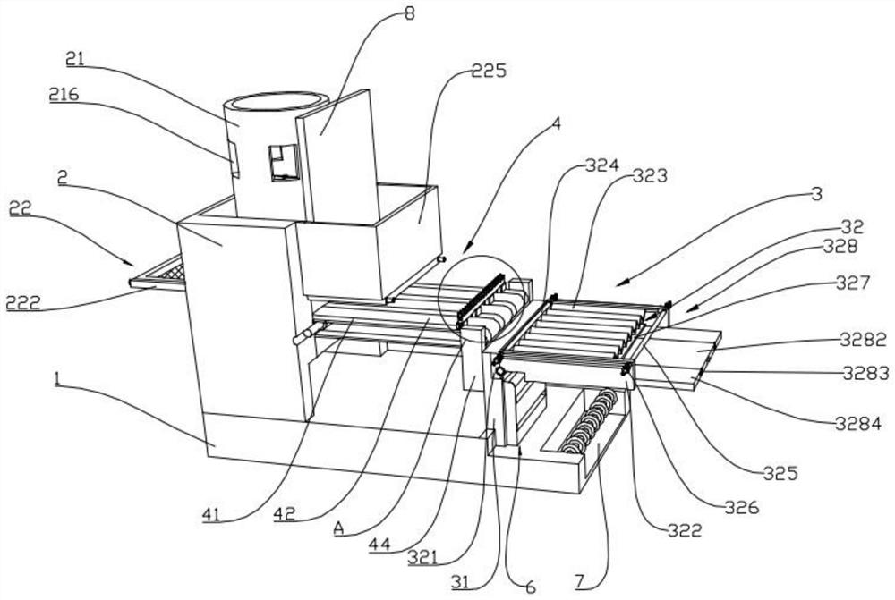
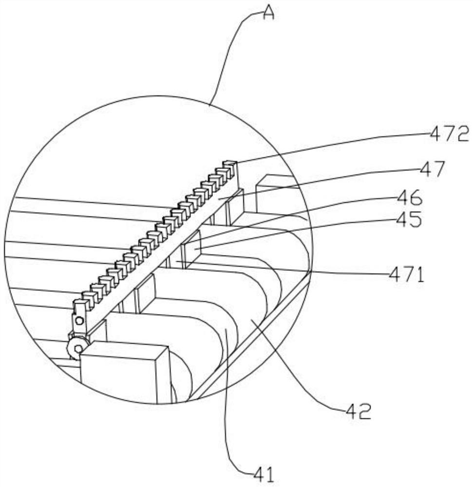
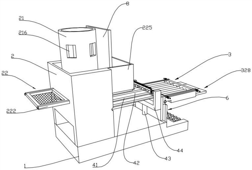
[0028] like Figure 1 to Figure 11 As shown, the present invention provides a raw material conveying device, including a conveying frame 1, one end of the conveying frame 1 is provided with a raw material unloading box 2, and the side wall of the top of the raw material unloading box 2 is provided with an auxiliary unloading box 225. The top and bottom of the unloading box 2 and the auxiliary unloading box 225 are both open-shaped, and a partition plate 8 is movably inserted at the connection between the raw material unloading box 2 and the auxiliary unloading box 225. Inside the raw material unloading box 2 The raw material barrel 21 and the sieve plate device 22 are sequentially arranged from top to bottom, and the raw material barrel 21 is slidably arranged between the top opening of the raw material unloading box 2 and the top opening of the auxiliary unloading box 225, and the other end of the conveying frame 1 is provided with There is a discharge collecting device 3, a ...
Embodiment 2
[0031] On the basis of the first embodiment, the discharging and collecting device 3 includes a discharging rack 31, the discharging rack 31 is fixedly arranged at the other end of the conveying rack 1, and the side wall of the discharging rack 31 is provided with a multi-variable material guide plate 32, The variable feed guide plate 32 includes an installation frame 321 movably arranged on the side wall of the discharge frame 31, a U-shaped bracket 322 is hinged on the installation frame 321, and a wave-shaped material plate 323 is arranged in the U-shaped opening of the U-shaped bracket 322 , and the two ends of the wave-shaped material plate 323 are respectively movable through to the outside of the two ends of the U-shaped opening of the U-shaped bracket 322. The U-shaped opening of the U-shaped bracket 322 is provided with a left guide rod 324 and a right guide rod 325 at intervals. The material guide plate 32 is located between the left guide rod 324 and the right guide ...
Embodiment 3
[0033]On the basis of the first embodiment, the screening and discharging device 6 includes an L-shaped fixed sieve plate 61, and the L-shaped fixed sieve plate 61 is arranged on one side of the discharge rack 31 in parallel and at intervals, and the L-shaped fixed sieve plate 61 is connected to the first The other end of the conveyor belt 41 corresponds to the other end of the second conveyor belt 42. The vertical end of the L-shaped fixed sieve plate 61 is sequentially provided with a number of screening grooves 62 from top to bottom. The screening grooves 62 are all provided with screens. The mesh 63 is divided, and the mesh number of the screening mesh 63 increases sequentially from top to bottom. The horizontal end of the L-shaped fixed sieve plate 61 is in conflict with the side wall of the discharge rack 31, and the horizontal end of the L-shaped fixed sieve plate 61 is embedded There is a fixed cylinder 64, a pusher plate 65 is arranged on the piston rod of the fixed cy...
PUM
 Abstract
Description
Claims
Application Information
 - R&D
- Intellectual Property
- Life Sciences
- Materials
- Tech Scout
- Unparalleled Data Quality
- Higher Quality Content
- 60% Fewer Hallucinations
Browse by: Latest US Patents, China's latest patents, Technical Efficacy Thesaurus, Application Domain, Technology Topic, Popular Technical Reports.
© 2025 PatSnap. All rights reserved.Legal|Privacy policy|Modern Slavery Act Transparency Statement|Sitemap|About US| Contact US: help@patsnap.com


