
Groove pressing structure and template system

A technology for pressing grooves and templates, which is applied in the direction of formwork/formwork/work frame, connection parts of formwork/formwork/work frame, building construction, etc., which can solve problems such as rotten roots and large sizes of metal parts, and achieve reduction Obstruction, cost reduction, and effect of improving the quality of groove forming

Pending Publication Date: 2022-07-15
SNTO TECH GRP
View PDF4 Cites 0 Cited by
  • Summary
  • Abstract
  • Description
  • Claims
  • Application Information

AI Technical Summary

Problems solved by technology

In addition, in order to keep the position of the metal parts stable, it is necessary to install a pressure plate on the metal parts, and the size of the pressure plate will be larger than the metal parts, resulting in the pouring concrete being difficult to flow around the metal parts due to the pressure plate blocking the concrete. Extensive root rot

Method used


Image

  • Groove pressing structure and template system
  • Groove pressing structure and template system
  • Groove pressing structure and template system

Examples


Embodiment Construction

[0066] The technical solutions in the embodiments of the present application will be described below with reference to the drawings in the embodiments of the present application. Obviously, the described embodiments are only a part of the embodiments of the present application, rather than all the embodiments.

[0067] It should be noted that when a component is considered to be "connected" to another component, it can be directly connected to another component or there may be an intervening component at the same time. When a component is considered to be "set on" another component, it may be located directly on the other component or may co-exist with an intervening component. The terms "top," "bottom," "top," "bottom," "left," "right," "front," "back," and similar expressions are used herein for illustrative purposes only.

[0068] When two elements (planes, lines) are arranged in parallel, it should be understood that the relationship between the two elements includes both ...


PUM


Abstract

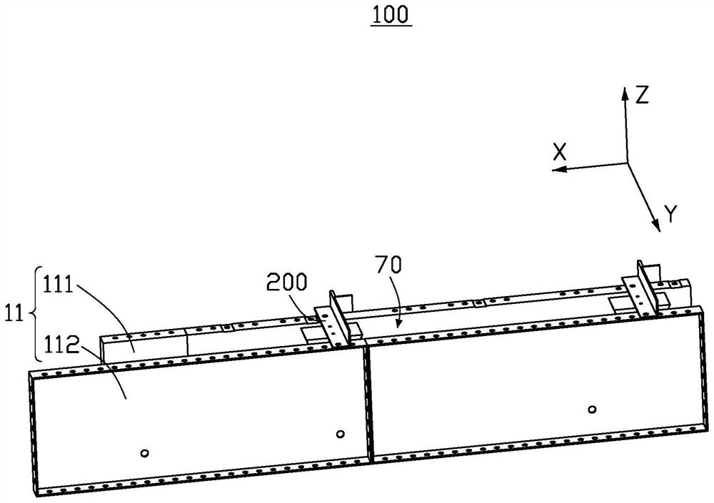
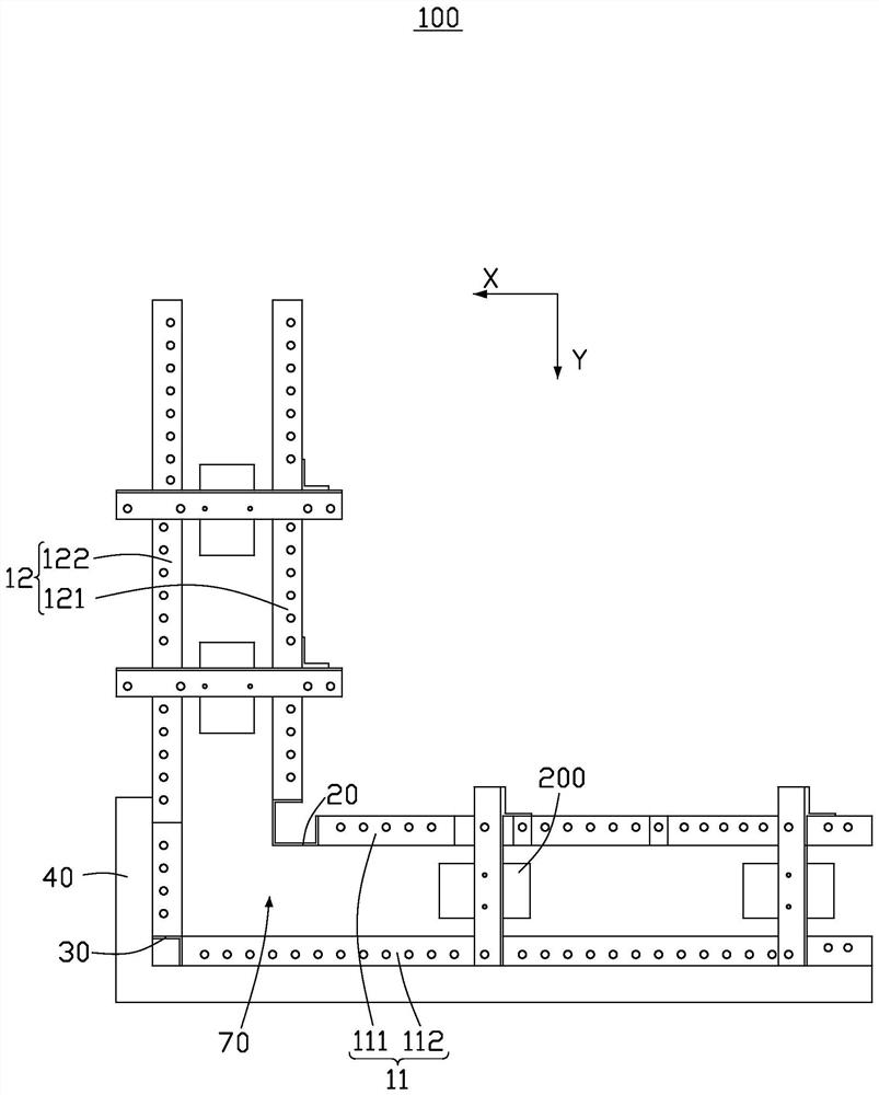
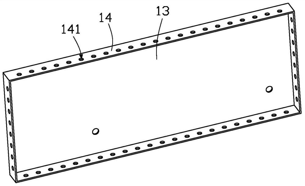
The invention relates to the field of buildings, in particular to a groove pressing structure and a formwork system.The groove pressing structure comprises a connecting piece and a groove pressing piece, and the connecting piece is used for being connected with a formwork. The groove pressing piece is arranged on one side of the connecting piece, at least part of the periphery, adjacent to the connecting piece, of the groove pressing piece is exposed out of the connecting piece, and the groove pressing piece is used for being arranged in concrete so that a pressing groove can be formed in the concrete. At least part of the periphery of the groove pressing piece can be exposed out of the connecting piece, so that concrete can conveniently flow to the periphery of the groove pressing piece and even can be directly poured to part of the periphery of the groove pressing piece, and compared with the mode that the periphery of the groove pressing piece is directly covered by the connecting piece, the concrete can better make contact with the groove pressing piece and be solidified, and the situation that the periphery of the groove pressing piece is rotted is reduced; and the groove pressing forming quality is improved.

Description

technical field [0001] The present application relates to the field of construction, in particular to a grooved structure and a formwork system. Background technique [0002] There are many places in the building that need to be slotted to allow for the subsequent installation of other structures. At present, a metal part is usually embedded in the place that needs to be grooved, and a pressure groove is preset on the metal part. After the concrete is poured, the concrete and the metal part solidify to complete the groove on the building. And in order to keep the position of the metal parts stable, a pressure plate needs to be installed on the metal parts, and the size of the pressure plate will be larger than that of the metal parts, which makes it difficult for the poured concrete to flow to the surrounding of the metal parts because the pressure plate blocks the concrete. Extensive root rot phenomenon. SUMMARY OF THE INVENTION [0003] In view of this, it is necessary...

Claims


Application Information

Patent Timeline
Patent Type & Authority Applications(China)
IPC IPC(8): E04G15/06E04G17/00
CPCE04G15/068E04G17/00
Inventor 彭福龙
Owner SNTO TECH GRP
Learn More