Liquid separation device for heat exchanger and heat exchanger

A heat exchanger and liquid separation technology, which is used in refrigeration and liquefaction, lighting and heating equipment, refrigerators, etc., can solve the problems of affecting heat exchange effect and uneven mixing of gas and liquid phases, preventing separation and improving heat exchange. The effect of efficiency

Pending Publication Date: 2022-07-15
QINGDAO HAIER AIR CONDITIONING ELECTRONICS CO LTD +2
View PDF0 Cites 0 Cited by
  • Summary
  • Abstract
  • Description
  • Claims
  • Application Information

AI Technical Summary

Problems solved by technology

[0006] The present invention aims to solve the above-mentioned technical problems, that is, to solve the problem that the existing heat e

Method used


Image

  • Liquid separation device for heat exchanger and heat exchanger
  • Liquid separation device for heat exchanger and heat exchanger
  • Liquid separation device for heat exchanger and heat exchanger

Examples


Example Embodiment

[0040] Example 1

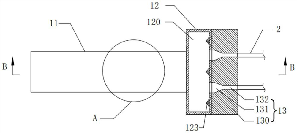
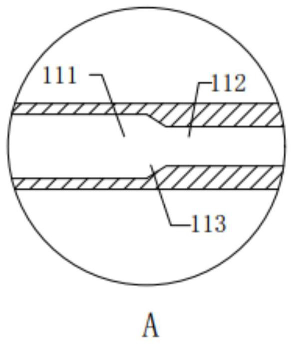
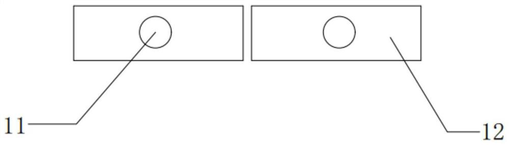
[0041] Combine below Figure 1 to Figure 3 The first embodiment of the present invention is introduced, wherein, figure 1 is a schematic structural diagram of Embodiment 1 of the liquid separation device of the present invention; figure 2 Yes figure 1 A partial enlarged view of the sectional view along the B-B line at A; image 3 Yesfigure 1 left view diagram.

[0042] like figure 1 As shown, the liquid separation device of the present invention includes a liquid inlet pipe 11, a liquid separation member 12 and a speed-increasing member 13. The liquid separation member 12 has a mixing chamber 120 in it, and the mixing chamber 120 is communicated with the liquid inlet pipe 11. The liquid-phase refrigerant entering the mixing chamber 120 is mixed with the gas-phase refrigerant, one end of the speed-increasing member 13 is communicated with the mixing chamber 120, and the other end of the speed-increasing member 13 is communicated with the heat exchange t...

Example Embodiment

[0088] Embodiment 2

[0089] Combine below Figure 4 to Figure 8 A second embodiment of the present invention is introduced, wherein, Figure 4 is a schematic structural diagram of Embodiment 2 of the liquid separating device of the present invention; Figure 5 Yes Figure 4 The schematic cross-sectional structure along the C-C line in the middle (the protruding structure is not shown); Image 6 Yes Figure 4 Schematic diagram of the cross-sectional structure along the D-D line in the middle; Figure 7 Yes Figure 4 A partial enlarged view of the sectional view along the F-F line at E; Figure 8 Yes Figure 4 left view diagram.

[0090] like Figure 4 As shown, the liquid separation device of the present invention includes a liquid inlet pipe 11, a liquid separation member 12 which is sequentially communicated with the liquid inlet pipe 11, and a speed-increasing member 13 communicated with the liquid separation member 12. The liquid separation member 12 includes a la...


PUM


Abstract

The invention relates to the technical field of heat exchange equipment, in particular to a liquid separation device for a heat exchanger and the heat exchanger, and aims to solve the problems that when a refrigerant enters a heat exchange pipe of an existing heat exchanger, gas-liquid two-phase mixing is not uniform, and the heat exchange effect is affected. In order to achieve the purpose, the liquid separation device for the heat exchanger comprises a liquid inlet pipe, a liquid separation component and a speed increasing component, the liquid separation component is provided with a mixing cavity, the mixing cavity communicates with the liquid inlet pipe, one end of the speed increasing component communicates with the mixing cavity, and the other end of the speed increasing component communicates with a heat exchange pipe of the heat exchanger; and the speed increasing component can enable the refrigerant in the mixing cavity to be quickly sprayed into the heat exchange tube. By means of the arrangement, when refrigerants enter the mixing cavity from the liquid inlet pipe, the gas-phase refrigerants and the liquid-phase refrigerants are evenly mixed, the gas-phase refrigerants and the liquid-phase refrigerants are prevented from being separated, the refrigerants in the mixing cavity are rapidly sprayed into the heat exchange pipes under the action of the speed increasing component, and therefore the heat exchange efficiency of the heat exchanger is improved.

Description

technical field [0001] The invention relates to the technical field of heat exchange equipment, and in particular provides a liquid separation device for a heat exchanger and a heat exchanger. Background technique [0002] The existing heat exchanger still has the problem of low heat exchange efficiency. [0003] Taking the dry evaporator as an example, the conventional dry evaporator does not study the tube-side liquid separation carefully, which leads to the partial condensation effect of most dry evaporators and the relatively poor evaporation effect, which greatly wastes the performance of the heat exchanger. So that the heat exchanger can not give full play to its effect. [0004] In the existing dry evaporator, the refrigerant has two-phase separation at the inlet, which leads to uneven mixing of gas and liquid two phases when the refrigerant enters the heat exchange tube, which affects the heat exchange effect of the heat exchanger. [0005] Therefore, a new technic...

Claims


Application Information

Patent Timeline
IPC IPC(8): F25B41/42F25B43/00
CPCF28F9/22
Inventor 孟庆良何建奇李银银倪双全宋强顾超
Owner QINGDAO HAIER AIR CONDITIONING ELECTRONICS CO LTD
Why Eureka
Try Eureka