Highly integrated engineering machinery control system based on CAN bus

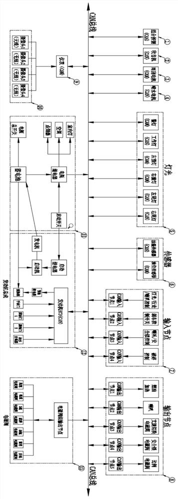
A CAN bus, construction machinery technology, applied in the field of electrical control, can solve the problems of no standard, system, comprehensive communication protocol, cumbersome wiring harness design, dense wiring and other problems, achieve information data display and fault alarm intelligence, reduce direct costs and Indirect cost, improve the effect of intelligent operation

Pending Publication Date: 2022-07-15
山东成文电子有限公司
View PDF0 Cites 0 Cited by
  • Summary
  • Abstract
  • Description
  • Claims
  • Application Information

AI Technical Summary

Problems solved by technology

[0002] In the field of construction machinery monitoring system, the current state of technology of similar products adopts ordinary mechanical methods such as knobs and switches, and directly controls the executive components through lines; electrical components, such as radios, lights, wiper motors, water sprays, etc. Motors, solenoid valves and other equipment are all independently controlled, and the operation is cumbersome; the sensors are all switch data or analog data; the design of the wiring harness is cumbersome, the wiring is complicated, and the wiring is dense, almost all of which are point-to-point design ideas
In the process of design, wiring, assembly, etc., it is extremely time-consuming, and the wiring harness materials are used too much, which wastes resources
[0003] In terms of the whole system: the control method is scattered, complex, low degree of integration, low product stability, all are single-loop control methods; no fault prompts, low degree of intelligence, resulting in extremely inconvenient operation and maintenance
[0004] In terms of electrical components: cumbersome control, low degree of intelligence, no electrical device failure alarm function
[0005] In terms of software: there is no standard, systematic and comprehensive communication protocol, resulting in a blank market
[0006] In terms of wiring harness design: there are problems such as high cost of raw materials, complex design, cumbersome process, and high man-hours for production and installation.

Method used


Image

  • Highly integrated engineering machinery control system based on CAN bus
  • Highly integrated engineering machinery control system based on CAN bus
  • Highly integrated engineering machinery control system based on CAN bus

Examples


Embodiment Construction

[0034] The technical solutions in the embodiments of the present invention will be clearly and completely described below with reference to the accompanying drawings in the embodiments of the present invention. Obviously, the described embodiments are only some, but not all, embodiments of the present invention. The following description of at least one exemplary embodiment is merely illustrative in nature and is in no way intended to limit the invention, its application, or uses. Based on the embodiments of the present invention, all other embodiments obtained by those of ordinary skill in the art without creative efforts shall fall within the protection scope of the present invention.

[0035] It should be noted that the terminology used herein is for the purpose of describing specific embodiments only, and is not intended to limit the exemplary embodiments according to the present application. As used herein, unless the context clearly dictates otherwise, the singular is i...


PUM


Abstract

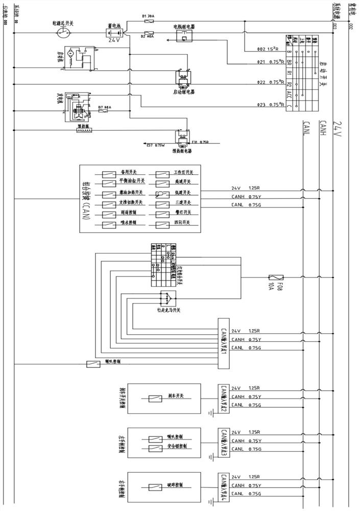
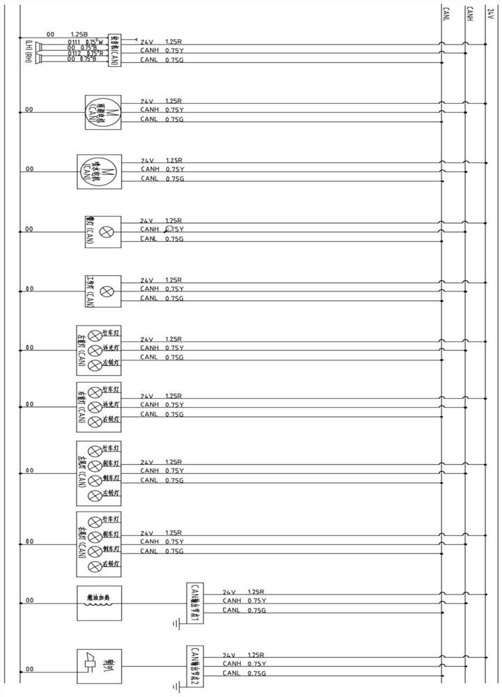
The invention discloses a highly integrated engineering machinery control system based on a CAN (Controller Area Network) bus, which comprises a combined key (CAN), a radio (CAN), a wiper motor (CAN), a water spray motor (CAN), a light (CAN), a sensor (CAN), an input node (CAN), an output node (CAN), an instrument (CAN), an engine unit (engine ECU (Electronic Control Unit)), an electromagnetic valve output node (CAN) and an engine bus. The system is characterized in that the combined button (CAN), the radio (CAN), the wiper motor (CAN), the water spray motor (CAN), the light (CAN), the sensor (CAN), the input node (CAN), the output node (CAN), the instrument (CAN), the engine ECU (CAN) and the solenoid valve output node (CAN) are all connected in parallel through a CAN bus.

Description

technical field [0001] The invention relates to the technical field of electrical control, in particular to a highly integrated engineering machinery control system based on a CAN bus. Background technique [0002] In the field of construction machinery monitoring systems, the technical status of similar products in terms of control methods, all use ordinary mechanical methods such as knobs and switches, and directly control the execution components through lines; electrical components, such as radios, lights, wiper motors, water spray Motors, solenoid valve groups and other equipment are all independently controlled and complicated to operate; sensors are all switch data or analog data; wiring harness design is cumbersome, wiring is complex, and wiring is dense, almost all point-to-point design ideas. In the process of design, wiring, assembly, etc., it is extremely time-consuming, and the wire harness raw materials are used too much, which wastes resources. [0003] In te...

Claims


Application Information

Patent Timeline
Patent Type & Authority Applications(China)
IPC IPC(8): G05B23/02
CPCG05B23/0213
Inventor 刘成文刘桂全孙静静
Owner 山东成文电子有限公司
Why Eureka
Try Eureka