Stainless steel tube structure of heating rod of electronic thermostat and forming process of stainless steel tube structure

A technology of stainless steel pipe and forming process, which is applied in the direction of ohmic resistance heating parts, heating element shape, etc., can solve the problems that the flange and the heating rod cannot be guaranteed, the flange and the heating rod are easy to desolder, and waste processing time, etc., to achieve The structure is simple, the processing is convenient, and the effect of saving production cost

Pending Publication Date: 2022-07-15
温州海得利电气有限公司
View PDF0 Cites 0 Cited by
  • Summary
  • Abstract
  • Description
  • Claims
  • Application Information

AI Technical Summary

Problems solved by technology

[0002] At present, when the heating rod of electronic thermostat is produced, the heating rod is processed first, and then the flange is welded. In traditional products, the heating rod and the flange are two independent parts, which are fixed as a whole by welding, but in actual use , there are many defects. First, the heating rod and the flange are processed in multiple processes, which wastes processing time, reduces processing efficiency, and also increases processing costs. Secondly, the flange and the heating rod are welded and fixed, which cannot ensure that the flange and the heating rod maintain Concentric, resulting in easy misalignment in the later installation, and the welding position of the flange and the heating rod is very easy to desolder, resulting in a direct impact on product quality in the later stage, so a stainless steel tube structure and its forming process for the electronic thermostat heating rod are needed. solve these problems

Method used


Image

  • Stainless steel tube structure of heating rod of electronic thermostat and forming process of stainless steel tube structure
  • Stainless steel tube structure of heating rod of electronic thermostat and forming process of stainless steel tube structure

Examples


Embodiment 1

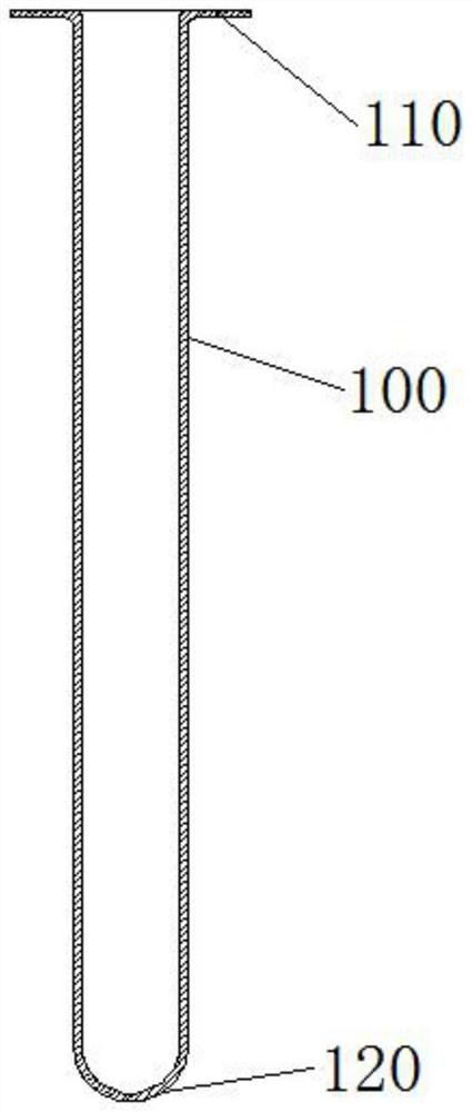
[0016] In the first embodiment, the other end of the tube body 100 is stamped by a die to form a sealed back cover 120 . In this embodiment, the other end of the tube body 100 is a sealed back cover 120 structure formed by die stamping, which can be combined with the tube body 100 and the tube body 100 . The flanging 110 structure is integrally stamped and formed, which greatly improves the processing efficiency.

Embodiment 2

[0017] The second embodiment, the difference between this embodiment and the first embodiment is that the other end of the pipe body 100 described in this embodiment is welded to form a sealed bottom cover 120, and the sealed bottom cover 120 of one end of the pipe body 100 is formed by welding, which can also be achieved. Same effect.

[0018] Among the above two embodiments, the first embodiment is preferably adopted, the processing procedure is simpler, the efficiency is higher, and the sealing performance is higher.

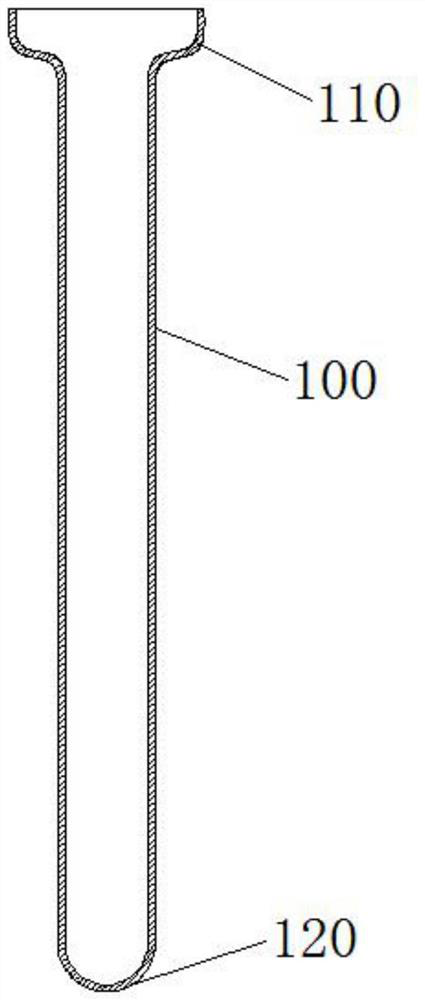
[0019] In this example figure 1 and figure 2 The pipe flanging structure shown is different in shape, but its function and the effect achieved are the same, all of which are used to replace the traditional flange structure.

[0020] The pipe body 100 and the flange 110 of the pipe body 100 are integrally stamped and formed by a stainless steel tube or a stainless steel plate. The everted bell mouth structure can be formed at the nozzle by lathe processing...


PUM


Abstract

The invention provides an electronic thermostat heating rod stainless steel pipe structure and a forming process thereof. The electronic thermostat heating rod stainless steel pipe structure comprises a pipe body, and one end of the pipe body is stamped through a die to form an outward flange; and the other end of the pipe body is stamped by a die to form a sealed back cover. According to the process, a pipe or a plate is placed in a stamping die to be integrally stamped to form a hollow pipe body with one end in a flanging horn mouth shape and the other end being a sealed bottom. The pipe or the plate is made of stainless steel. The stainless steel pipe is integrally stamped to form the hollow pipe body with one end in the shape of the outwards-turned horn mouth flange and the other end in the shape of the sealed bottom, the machining process is simplified, the production efficiency is improved, the production cost is saved, and the problem that the flange and the stainless steel pipe cannot be concentric in the traditional welding process is solved; concentricity of the two parts is ensured, sealing-off and the like are avoided, and follow-up installation and use of products are not affected.

Description

technical field [0001] The invention relates to components of a heating rod of an electronic thermostat, in particular to a stainless steel tube structure of the heating rod of an electronic thermostat and a forming process thereof. Background technique [0002] At present, the heating rod of electronic thermostat is processed first, and then the flange is welded. In traditional products, the heating rod and the flange are two independent parts, which are fixed as a whole by welding, but in actual use , there are many defects. First, the heating rod and the flange are processed in multiple processes, which wastes processing time, reduces the processing efficiency, and increases the processing cost. Secondly, the flange and the heating rod are welded and fixed, which cannot guarantee the flange and the heating rod. The concentricity leads to easy deviation in the later installation, and the welding position between the flange and the heating rod is very easy to be de-soldered...

Claims


Application Information

Patent Timeline
Patent Type & Authority Applications(China)
IPC IPC(8): H05B3/02H05B3/40
CPCH05B3/02H05B3/40H05B2203/017
Inventor 高凡
Owner 温州海得利电气有限公司
Why Eureka
Try Eureka