Line of sight detection method, line of sight detection device, and control program

A line-of-sight detection and line-of-sight technology, which is applied in image analysis, image enhancement, instruments, etc., can solve problems such as lack of specific consideration of line-of-sight detection methods, inattention, and difficulty in detecting line-of-sight directions

Pending Publication Date: 2022-07-15
株式会社燕孵 +1
View PDF2 Cites 0 Cited by
  • Summary
  • Abstract
  • Description
  • Claims
  • Application Information

AI Technical Summary

Problems solved by technology

[0005] However, it is difficult for the non-contact line-of-sight detection technology to accurately detect the eye in the case of using a face image representing one side of the face, in other words, when only one eye can be detected from the face image. Detect gaze direction
For this reason, for example, for an object placed on the side with respect to the direction of travel of a pedestrian, there is a problem that it is difficult to judge the degree of gaze or the presence or absence of inattention based on the line of sight information of the pedestrian.
The non-contact line-of-sight detection technology disclosed in Patent Document 1 and Patent Document 2 does not specifically consider the line-of-sight detection method when only one eye can be detected.

Method used


Image

  • Line of sight detection method, line of sight detection device, and control program
  • Line of sight detection method, line of sight detection device, and control program
  • Line of sight detection method, line of sight detection device, and control program

Examples


no. 1 approach

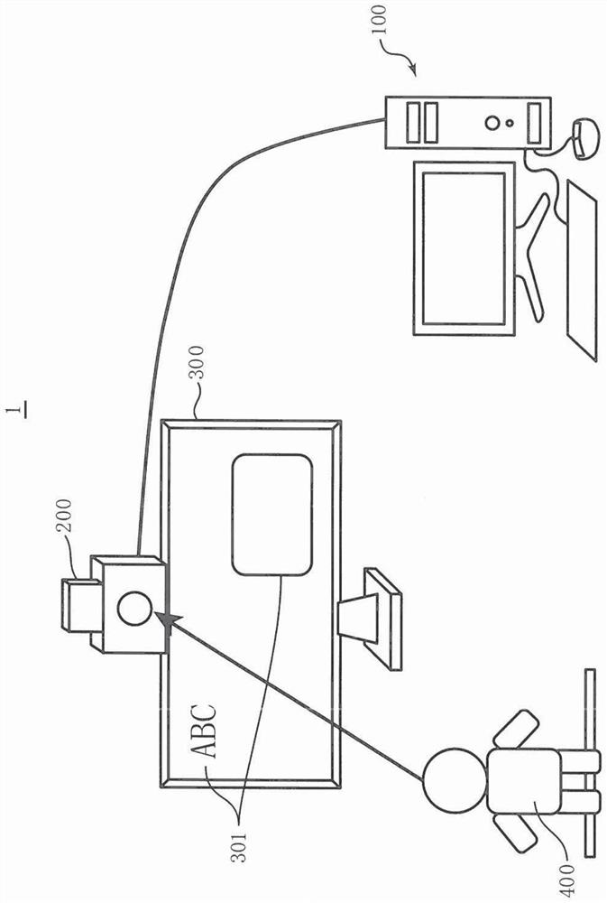
[0061] figure 1 It is a schematic diagram showing an example of the overall configuration of the image processing system 1 according to the first embodiment of the present invention. The image processing system 1 is a system that captures an image of a person 400 and detects line-of-sight information representing the line of sight of the person 400 from the obtained image data of the person 400 . exist figure 1 In this example, the image processing system 1 determines which target 301 among the plurality of targets 301 displayed on the display device 300 is being gazed by the person 400 . However, this is just an example, and the image processing system 1 can specify not only the object 301 displayed on the display screen of the display device 300 but also the object 301 that the person 400 is looking at in the actual space.

[0062] exist figure 1 In this example, the image processing system 1 is applied to a digital signage system. Therefore, the object 301 displayed on ...

no. 2 approach

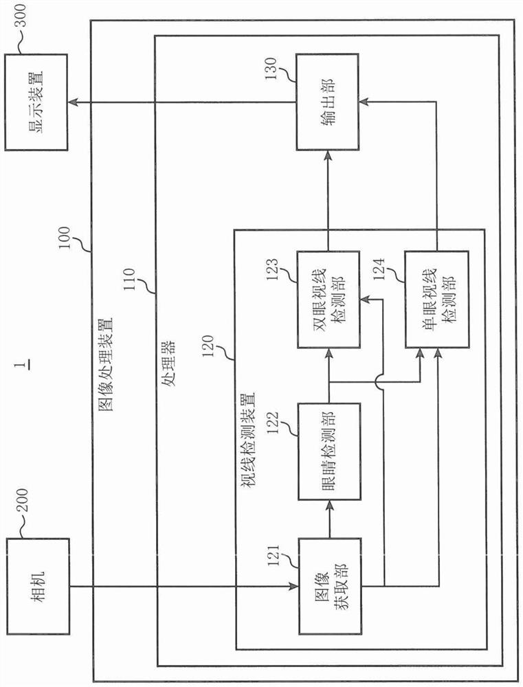
[0140] The second embodiment is an embodiment for estimating the degree of interest of the person 400 . Figure 14 It is a block diagram showing the detailed configuration of the image processing system 1A according to the second embodiment. In this embodiment, the same reference numerals are given to the same components as those in the first embodiment, and the description thereof will be omitted. Moreover, in Figure 14 , for and figure 2 Modules with the same name but different functions are given the symbol A at the end.

[0141] The sight line detection device 120A further includes a feature point detection unit 140 and an interest degree estimation unit 150 .

[0142] The feature point detection unit 140, and the hair detection unit 42 ( image 3 ) Similarly, the face region 60 including at least a part of the face of the person 400 is detected from the image data acquired from the image acquisition section 121 using a classifier created in advance for detecting the...


PUM


Abstract

The line-of-sight detection method obtains image data of the face of a person; detecting a left eye region including a left eye of a person and a right eye region including a right eye of the person from the image data of the face; detecting at least one of an ear region including a person's ear and a hair region including a person's hair from the image data of the face when only one of the right eye region and the left eye region can be detected; detecting information indicating the orientation of the face on the basis of information indicating the position of one eye included in the one eye region and information indicating the position of at least one of the position of the ear included in the ear region and the position of the hair included in the hair region; on the basis of information indicating the position of one eye and information indicating the orientation of the face, information indicating the line of sight of a person is detected.

Description

technical field [0001] The present invention relates to a technique for detecting a person's line of sight. Background technique [0002] The line of sight detection technology is used for various purposes such as estimation of objects of interest to a person, estimation of a person's state such as drowsiness, and a user interface that performs input to a device through line of sight. Line-of-sight detection technology is roughly divided into head-mounted type and non-contact type. The head-mounted line-of-sight detection technology is a technology for detecting line-of-sight by attaching a device such as a head-mounted display to a person's head. The non-contact line-of-sight detection technology is a technology that can detect line-of-sight without wearing the device to the human body. Since the non-contact line-of-sight detection technology does not require the device to be worn on the head as in the head-mounted line-of-sight detection technology, it has the advantage ...

Claims


Application Information

Patent Timeline
Patent Type & Authority Applications(China)
IPC IPC(8): G06T7/70
CPCG06T1/00G06V40/193G06V40/165G06T7/73G06V40/171G06V40/161G06T2207/30201
Inventor 大野寿和
Owner 株式会社燕孵
Why Eureka
Try Eureka