
Shock absorber

A technology of shock absorbers and stoppers, applied in the direction of shock absorbers, springs/shock absorbers, shock absorbers, etc., can solve problems such as reduced ride comfort, reduced ride comfort, product failure, etc., to improve ride quality Comfort, reduced contact noise, easy application effect

Pending Publication Date: 2022-07-19
HL MANDO CORP
View PDF0 Cites 0 Cited by
  • Summary
  • Abstract
  • Description
  • Claims
  • Application Information

AI Technical Summary

Problems solved by technology

Therefore, it becomes the cause of product failure, noise, and reduced ride comfort
[0008] Moreover, since the damping force adjustment function is not provided when the stroke is extended, the ride comfort is reduced when the damping force is reduced

Method used


Image

  • Shock absorber
  • Shock absorber
  • Shock absorber

Examples


Embodiment Construction

[0041] Hereinafter, embodiments of the present invention will be described in detail with reference to the accompanying drawings. The following embodiments are provided in order to fully convey the idea of ​​the present invention to those skilled in the art to which the present invention pertains. The present invention is not limited to the embodiments presented here, but can also be embodied in other forms. In the drawings, in order to clarify the present invention, parts irrelevant to the description may be omitted, and the sizes of components may be appropriately exaggerated to aid understanding.

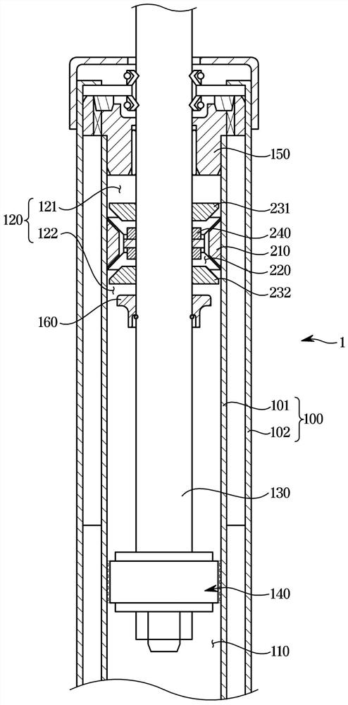
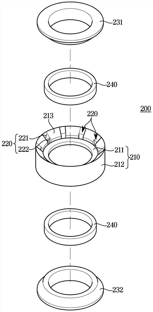
[0042] figure 2 is a cross-sectional view showing a shock absorber according to an embodiment of the present invention, image 3 is an exploded perspective view showing a flow piston valve provided in a shock absorber according to an embodiment of the present invention, Figure 4 It is a partial enlarged view showing the flow piston valve provided in the shock absorber accord...


PUM


Abstract

The invention relates to a shock absorber. According to one aspect of the present invention, there may be provided a shock absorber comprising: a cylinder filled with a fluid; a piston valve which is installed on a piston rod that reciprocates inside the cylinder and divides the space inside the cylinder into an expansion chamber and a compression chamber; the guide rod is arranged at the upper part of the air cylinder so as to guide the piston rod to move; a stopper coupled to the outside of the piston rod; and a flow piston valve coupled through the piston rod, dividing the expansion chamber into an upper chamber and a lower chamber, and provided with a plurality of bypass flow paths to communicate the upper chamber and the lower chamber. Wherein, when the piston rod is in a stretching stroke, the limiting stopper partially clings to the flow piston valve from the lower part and raises the flow piston valve, so that the flow rate of the fluid passing through the bypass flow path is adjusted.

Description

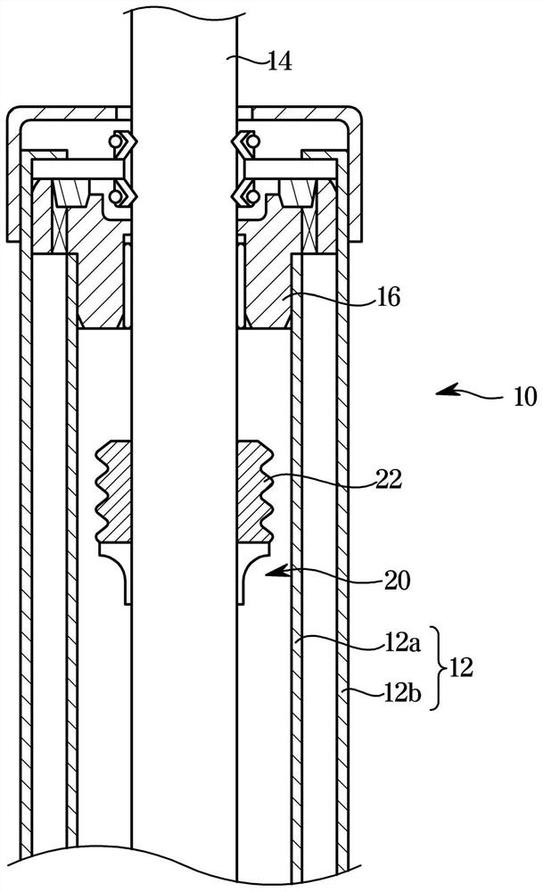
technical field [0001] The present invention relates to a shock absorber, and more particularly, to a shock absorber that can improve ride comfort and reduce noise during a rebound (extension) stroke. Background technique [0002] Usually, a buffer device is provided on the vehicle to buffer the shock or vibration received by the axle from the road surface during driving to improve the ride comfort, and the shock absorber is used as one of such buffer devices. [0003] figure 1 is a cross-sectional view showing a shock absorber according to the related art. refer to figure 1 , the shock absorber 10 is disposed between the axle and the vehicle body, and includes a cylinder 12 , and a piston rod 14 is movably disposed in the cylinder 12 . The cylinder 12 may be formed as a single tube, or may be formed as a double tube structure consisting of an inner tube 12a and an outer tube 12b. [0004] Also, a guide rod 16 is provided on the upper part of the cylinder 12 to keep cons...

Claims


Application Information

Patent Timeline
Patent Type & Authority Applications(China)
IPC IPC(8): F16F9/06F16F9/32F16F9/516
CPCF16F9/062F16F9/3207F16F9/516
Inventor 朱明
Owner HL MANDO CORP
Learn More