
Partitioned spraying desulfurization tower and desulfurization device

A technology for desulfurization towers and spray components, which is applied in the field of partitioned spray desulfurization towers and desulfurization devices, can solve the problems of reducing the desulfurization agent use effect and desulfurization efficiency of desulfurization towers, and achieve the effect of saving resources and improving effects

Active Publication Date: 2022-07-22
苍南伟明环保能源有限公司
View PDF6 Cites 0 Cited by
  • Summary
  • Abstract
  • Description
  • Claims
  • Application Information

AI Technical Summary

Problems solved by technology

[0006] The technical problem to be improved by the present invention: it is impossible to flexibly adjust the space size of each sub-spray area according to the sulfur content in the exhaust gas, and then adjust the exhaust gas in different spray areas. The residence time of the desulfurization agent is used to achieve the best spray desulfurization time ratio and desulfurization agent loss ratio, thereby reducing the use of desulfurization agent and the desulfurization efficiency of the desulfurization tower

Method used

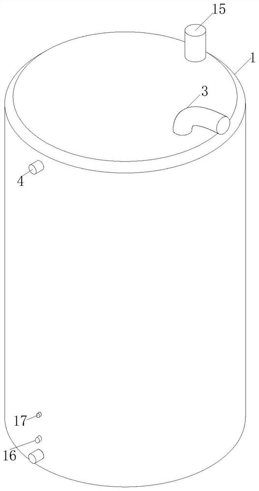
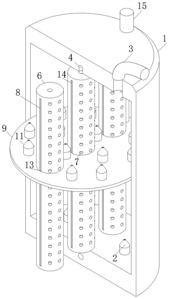
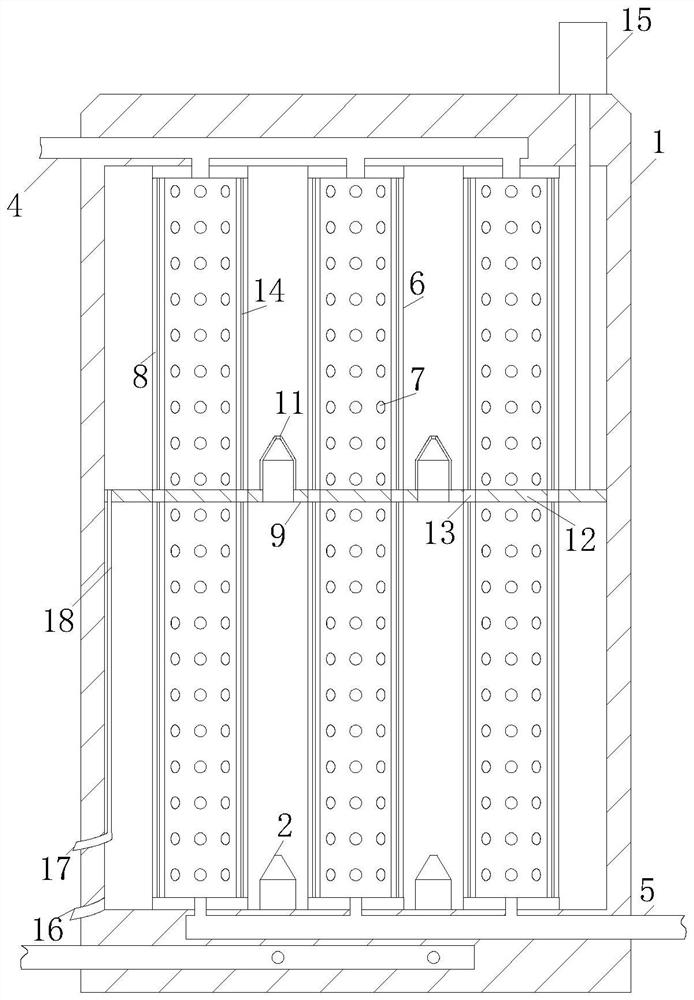

Image

  • Partitioned spraying desulfurization tower and desulfurization device
  • Partitioned spraying desulfurization tower and desulfurization device
  • Partitioned spraying desulfurization tower and desulfurization device

Examples


Embodiment approach

[0050] As an embodiment of the present invention, the spray assembly includes:

[0051] No. 1 pipeline 4; the No. 1 pipeline 4 is arranged in the wall thickness of the top of the tank body 1;

[0052] The No. 2 pipeline 5; the No. 2 pipeline 5 is arranged in the bottom wall thickness of the tank body 1;

[0053] The hollow tube 6; the two ends of the hollow tube 6 are respectively fixed to the inner wall of the top of the tank body 1 and the inner wall of the bottom of the tank body 1;

[0054] Hole 7; the hole 7 is opened on the hollow tube 6.

[0055] As an embodiment of the present invention, the partition component includes:

[0056] groove 8; the groove 8 is opened on the hollow tube 6;

[0057] The isolation disc 9; the isolation disc 9 is sleeved on the hollow tube 6; and is slidably connected with the outer wall of the hollow tube 6; the outer side of the isolation disc 9 is attached to the inner wall of the tank body 1;

[0058] No. 2 air intake pipe 11; the No. 2 a...


PUM


Abstract

The invention relates to the technical field of chemical engineering, in particular to a partitioned spraying desulfurizing tower and a desulfurizing device.The partitioned spraying desulfurizing tower comprises a tank body, and a first air inlet pipe is fixedly connected to the bottom of the tank body; the first gas inlet pipe is communicated with external flue gas through a gas channel; the layering assembly is positioned in the tank body and is used for layering flue gas entering the tank body; the spraying assembly is positioned in the tank body; the flue gas desulfurization assembly is used for desulfurizing flue gas in each layer after the layering assembly; the gas outlet pipe penetrates through the top of the tank; through cooperation of the spraying assembly and the layering assembly, the volume of the spraying section in the tank body can be flexibly adjusted through movement of the layering assembly, and the problem that the space size of each subarea spraying area cannot be flexibly adjusted according to the content of sulfur in waste gas through fixed subarea spraying is solved; further, the residence time of the flue gas in different spraying areas is adjusted, so that the optimal spraying desulfurization time proportion and the optimal desulfurization agent loss proportion are achieved, and the use effect of the desulfurization agent and the desulfurization efficiency of the desulfurization tower are improved.

Description

technical field [0001] The invention relates to the technical field of chemical industry, in particular to a zone spray desulfurization tower and a desulfurization device. Background technique [0002] The desulfurization tower is a tower-type equipment for desulfurization treatment of industrial waste gas; the main operation mode of the waste gas purification spray tower is that the acid mist waste gas is introduced into the purification tower through the air duct, and the waste gas and the sodium hydroxide absorption liquid undergo a gas-liquid two-phase process through the packing layer. The phase is fully contacted to absorb and neutralize the reaction. After the acid mist exhaust gas is purified, it is dewatered and demisted by the defogging plate and then discharged into the atmosphere by the fan; [0003] The absorption liquid is pressurized by the water pump at the bottom of the tower and sprayed down at the top of the tower, and finally returned to the bottom of the...

Claims


Application Information

Patent Timeline
Patent Type & Authority Applications(China)
IPC IPC(8): B01D53/48B01D53/75B01D53/78B01D53/79
CPCB01D53/48B01D53/75B01D53/78B01D53/79
Inventor 陈钦标庄和进魏为顺
Owner 苍南伟明环保能源有限公司
Learn More