
Welding tool clamp for manufacturing alloy pipe truss structure

A technology for welding fixtures and truss structures, applied in manufacturing tools, welding equipment, auxiliary welding equipment, etc., can solve the problems of easy deviation of connecting pipes or main frames, difficult to maintain the stability of connecting pipes, and low efficiency of truss structures. , to avoid welding quality, increase friction, and improve welding efficiency.

Active Publication Date: 2022-07-22
江苏神铸智能科技有限公司
View PDF10 Cites 0 Cited by
  • Summary
  • Abstract
  • Description
  • Claims
  • Application Information

AI Technical Summary

Problems solved by technology

[0003] There are two types of welding connection between the connecting pipe and the main frame: vertical and inclined. The overall force of the truss is balanced through the connecting pipe in two states. During the vertical welding and inclined welding of the connecting pipe, the connection The relative stability between the tube and the main frame will directly affect the welding effect. The easier the connecting tube or the main frame is to shift, the lower the quality of the final weld will be. If the connecting tube is supported manually during welding, the connection The stability of the tube is more difficult to maintain
[0004] In addition, the main frame is usually welded with several connecting pipes, and the efficiency of the overall formation of the truss structure is low in the case of welding a single side end successively

Method used


Image

  • Welding tool clamp for manufacturing alloy pipe truss structure
  • Welding tool clamp for manufacturing alloy pipe truss structure
  • Welding tool clamp for manufacturing alloy pipe truss structure

Examples


Embodiment Construction

[0038] The technical solutions in the embodiments of the present invention will be clearly and completely described below with reference to the accompanying drawings in the embodiments of the present invention. Obviously, the described embodiments are only a part of the embodiments of the present invention, but not all of the embodiments. Based on the embodiments of the present invention, all other embodiments obtained by those of ordinary skill in the art without creative efforts shall fall within the protection scope of the present invention.

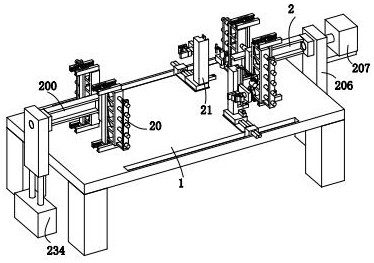
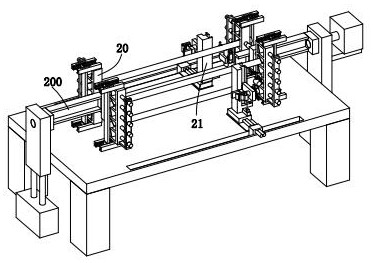
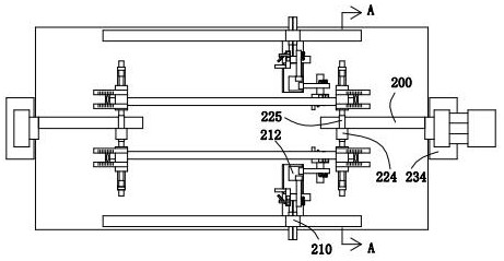
[0039] see figure 1 , figure 2 and image 3 , a welding fixture made of an alloy pipe truss structure, including a welding table 1 and a clamping end 2, the upper end of the welding table 1 is provided with a clamping end 2, and the clamping end 2 includes a clamping part 20 and an auxiliary welding The clamping parts 20 are symmetrically arranged above the welding table 1 , and the auxiliary welding parts 21 are located between th...


PUM


Abstract

The invention relates to the field of alloy pipe truss structure machining, in particular to an alloy pipe truss structure manufacturing welding tool clamp which comprises a welding table and a clamping end, under the condition that a clamping part and an auxiliary welding part are utilized, welding forming operation of an alloy pipe truss structure can be synchronously and bidirectionally carried out, and the welding efficiency of the alloy pipe truss structure is improved. The welding efficiency is improved, the truss structure can be automatically turned over while being kept in a clamped state, so that the alloy pipe truss structure is integrally formed, the adopted auxiliary welding part can be integrally matched with manual work to achieve vertical welding connection of the connecting pipe on the truss main body frame, and during welding connection, the welding efficiency is improved, and the welding efficiency is improved. By means of the auxiliary welding part, it can be guaranteed that the connecting pipe is in a vertical state all the time, it is avoided that the connecting pipe deviates to affect the welding quality, in addition, on the basis that the auxiliary clamping part has the assembling function, the auxiliary welding part can be matched with manual work to achieve inclined welding of the connecting pipe to the truss body frame, and the inclined state of the connecting pipe is kept in the welding period.

Description

technical field [0001] The invention relates to the field of alloy pipe fitting truss structure processing, in particular to a welding fixture for making an alloy pipe fitting truss structure. Background technique [0002] Pipe truss is a lattice structure formed by welding a main frame composed of multiple pipes of equal length and short-sized connecting pipes. It is often used to make simply supported trusses, arches, frames and towers. [0003] The welding state of the connecting pipe and the main frame has two types: vertical and inclined. The force of the whole truss is balanced by the connecting pipe in the two states. During the vertical welding and inclined welding of the connecting pipe, the connection The relative stability between the pipe and the main frame will directly affect the welding effect. The more easily the connecting pipe or the main frame is offset, the lower the quality of the final weld. The stability of the tube is more difficult to maintain. [...

Claims


Application Information

Patent Timeline
IPC IPC(8): B23K37/04B23K37/053B23K101/06
CPCB23K37/0443B23K37/053B23K2101/06
Inventor 李惠莲
Owner 江苏神铸智能科技有限公司
Learn More