Full-flexible bionic pneumatic manipulator based on branch-imitating structure

A pneumatic, manipulator technology, applied in the field of robotics, which can solve the problems of damage to the grasped object, low grasping rate, unsafe grasping, etc., to achieve fast deformation process, increase contact area, and high grasping rate. Effect

Pending Publication Date: 2022-07-22
ANHUI UNIVERSITY
View PDF8 Cites 0 Cited by
  • Summary
  • Abstract
  • Description
  • Claims
  • Application Information

AI Technical Summary

Problems solved by technology

[0007] 1. This kind of manipulator is only composed of two left and right air chambers. Although each air chamber can be independently controlled to achieve various telescopic and bending actions, because the two air chambers are connected by a diaphragm, the deformation of telescopic and bending is limited. When one air cavity is individually controlled to fine-tune the degree of deformation of the manipulator, the other air cavity will be affected, resulting in unstable grasping, which may cause damage to the grasped object, and cannot grasp the object more dexterously;
[0008] 2. The area of ​​the manipulator in contact with the object is limited, and the force point of the grasp is relatively concentrated, which leads to the inability to safely grasp some objects with smooth surfaces and large shapes, and a single manipulator cannot pinch and clamp The operation of picking can only be used for picking and wrapping, and the method of use is single
[0009] 3. The manipulator adopts a bionic clover structure. In the process of inflating the manipulator, because the free end of the front manipulator is relatively short, that is, the unconnected part of the front end of the clover petals is relatively short, which will cause the manipulator to deform slowly. low rate

Method used


Image

  • Full-flexible bionic pneumatic manipulator based on branch-imitating structure
  • Full-flexible bionic pneumatic manipulator based on branch-imitating structure
  • Full-flexible bionic pneumatic manipulator based on branch-imitating structure

Examples


Embodiment Construction

[0028] In order to make the purposes, technical solutions and advantages of the embodiments of the present invention clearer, the technical solutions in the embodiments of the present invention will be clearly and completely described below with reference to the accompanying drawings in the embodiments of the present invention. Obviously, the described embodiments These are some embodiments of the present invention, but not all embodiments. Based on the embodiments of the present invention, all other embodiments obtained by persons of ordinary skill in the art without creative efforts shall fall within the protection scope of the present invention.

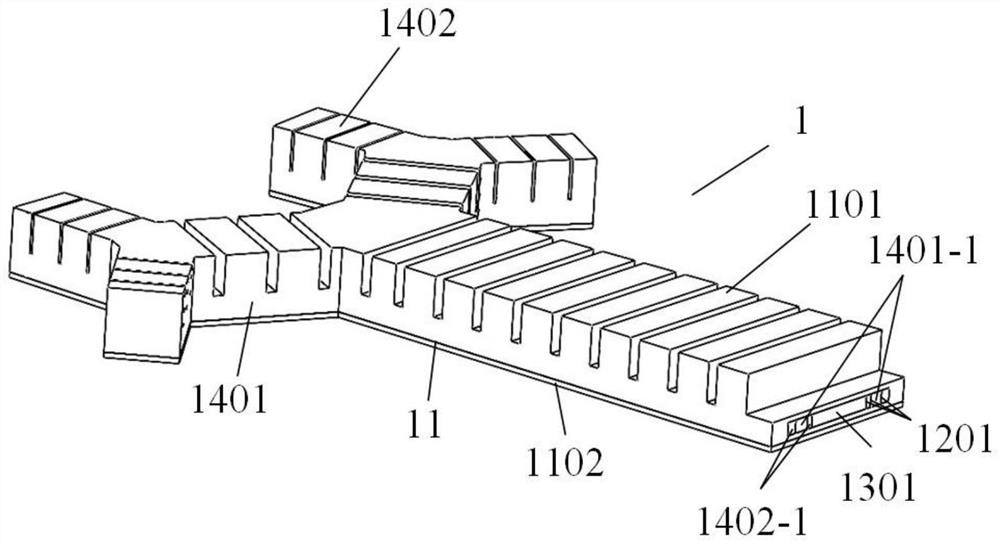
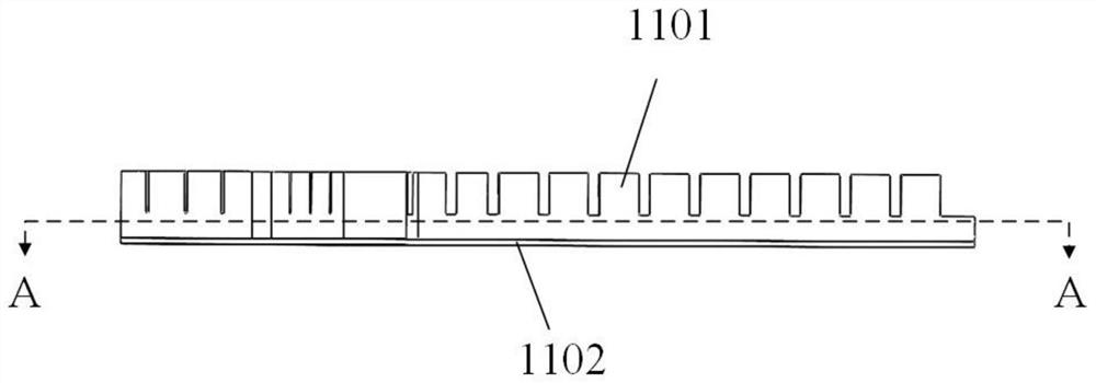
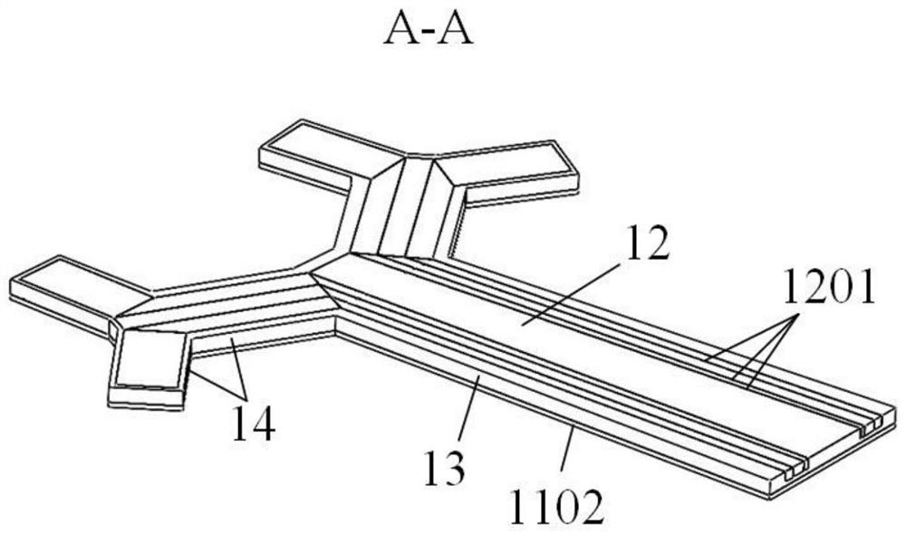
[0029] Figure 1 to Figure 5 A schematic structural diagram of a preferred embodiment of the present invention is shown. In the figure, a fully flexible bionic pneumatic manipulator based on a tree-like structure includes a pneumatic drive unit and a manipulator unit 1 controlled independently. The manipulator unit 1 It includes ...


PUM


Abstract

A full-flexible bionic pneumatic manipulator based on a bionic branch structure comprises a pneumatic driving unit and manipulator units controlled independently, each manipulator unit comprises a shell with the overall shape of a bionic branch structure, and at least one surface of the shell in the length direction is of a zigzag structure; the inner part of the shell is provided with a cavity with a consistent shape, a strain limiting layer is also laminated on the surface of the shell at a position opposite to the zigzag structure, the shell and the strain limiting layer are both made of flexible materials, and the strain limiting layer is made of flexible materials of which the Young modulus is greater than that of the cavity; the shell and the cavity of the bionic branch structure are each composed of a first-stage main branch part and a plurality of stages of branch parts, the number of branches of the multiple stages of branch parts is gradually increased according to a preset rule, and the cavity of the branch of each branch part is connected with the pneumatic driving unit and is independent of the pneumatic driving unit. According to the robot, more types of objects can be stably, nondestructively and flexibly grabbed, the response time is shorter, the deformation process is faster, and the grabbing speed is higher.

Description

Technical field: [0001] The invention relates to a flexible bionic pneumatic manipulator, in particular to a fully flexible bionic pneumatic manipulator based on a tree-like structure, belonging to the technical field of robotics. Background technique [0002] It is well known that, with the continuous development of computer technology, control technology, and artificial intelligence technology, robots play an increasingly important role in the fields of intelligent manufacturing, medical technology, aerospace and other fields. Traditional manipulators are usually composed of rigid parts and rigid joints, with limited degrees of freedom, can only be used to perform a single task, and lack adaptability to the environment. Moreover, most of the traditional manipulators are made of metal materials, which are generally in rigid contact with the object being grasped, and lack necessary flexibility. With the further development of soft materials, intelligent robots are developin...

Claims


Application Information

Patent Timeline
Patent Type & Authority Applications(China)
IPC IPC(8): B25J15/00B25J15/12
CPCB25J15/0023B25J15/12
Inventor 郭小辉李翠翠武永慈杜鑫会王铭朱康利李杰兵黄承鹏洪琪张红伟
Owner ANHUI UNIVERSITY
Why Eureka
Try Eureka