
Aeration device for treating domestic sewage

A technology of aeration device and domestic sewage, which is applied in water aeration, biological water/sewage treatment, water/sludge/sewage treatment, etc., can solve the problems of decreased reaction rate, trouble, accelerated transfer, etc., to improve microbial activity , Improve aeration efficiency and prevent clogging

Pending Publication Date: 2022-07-22
清远市德晟嘉恒能源环保工程有限责任公司
View PDF0 Cites 2 Cited by
  • Summary
  • Abstract
  • Description
  • Claims
  • Application Information

AI Technical Summary

Problems solved by technology

[0002] In the process of sewage treatment, air is forced into the sewage for aeration, so that the sewage in the pool is contacted with air to oxygenate, and the liquid is stirred to accelerate the transfer of oxygen in the air to the liquid, and strengthen the organic matter, microorganisms and dissolved oxygen in the pool. Contact, to oxidize and decompose organic matter in sewage; in winter or in northern regions due to the cold climate, the microbial activity is not high, resulting in a decrease in the reaction rate;
[0003] In addition, due to the large amount of suspended solids in the sewage, there may even be a lot of sediment, and the aeration pipes are mostly located at the bottom. Even if the gas is continuously supplied to the inside of the aeration pipes, it is inevitable that the air outlets will be blocked. , and even particulate matter enters the inside of the pipe body from the air outlet, but most of the current aeration pipes do not have corresponding treatment structures. After long-term use, they need to be disassembled, which is relatively troublesome

Method used


Image

  • Aeration device for treating domestic sewage
  • Aeration device for treating domestic sewage
  • Aeration device for treating domestic sewage

Examples


Embodiment Construction

[0024] The technical solutions of the present invention will be further described below with reference to the accompanying drawings and through specific embodiments.

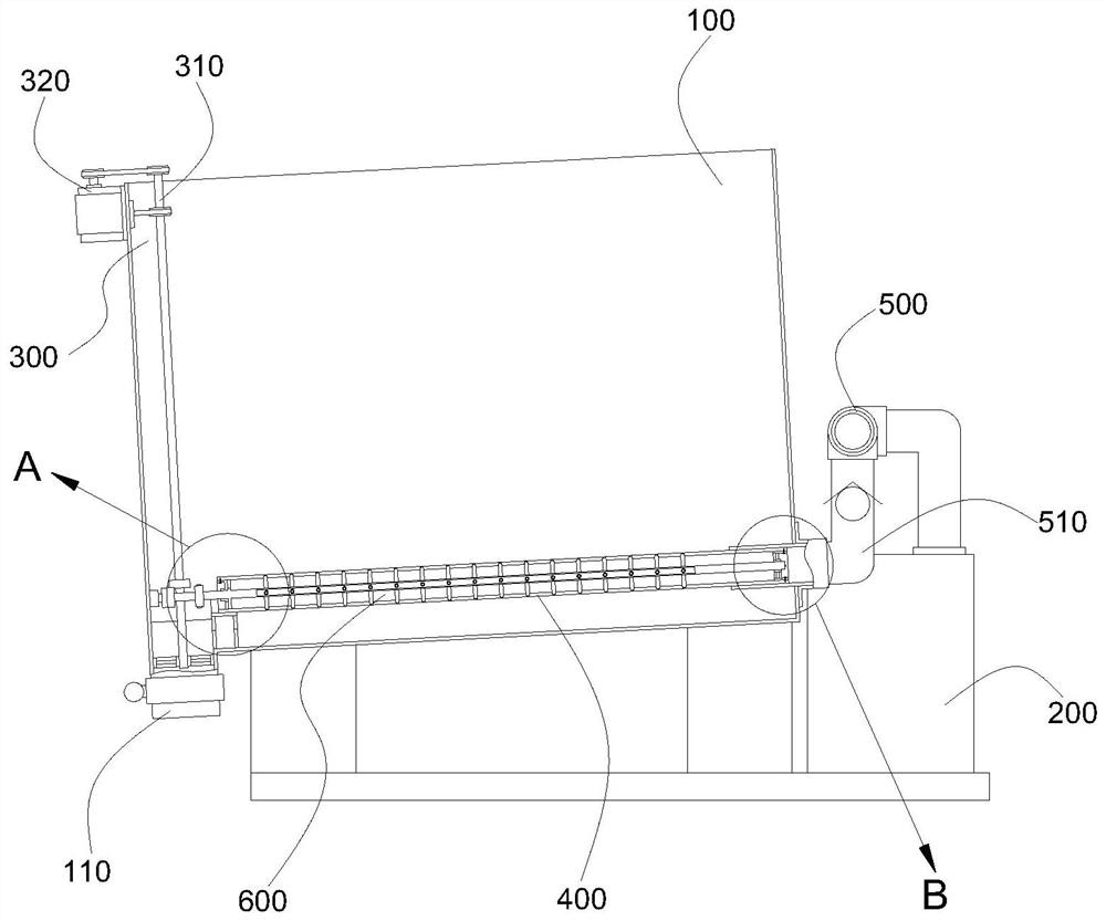
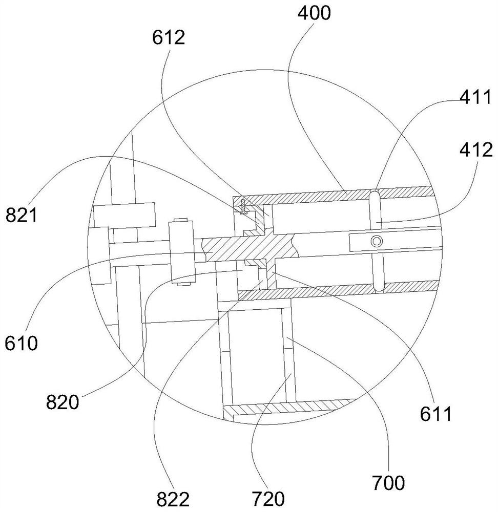
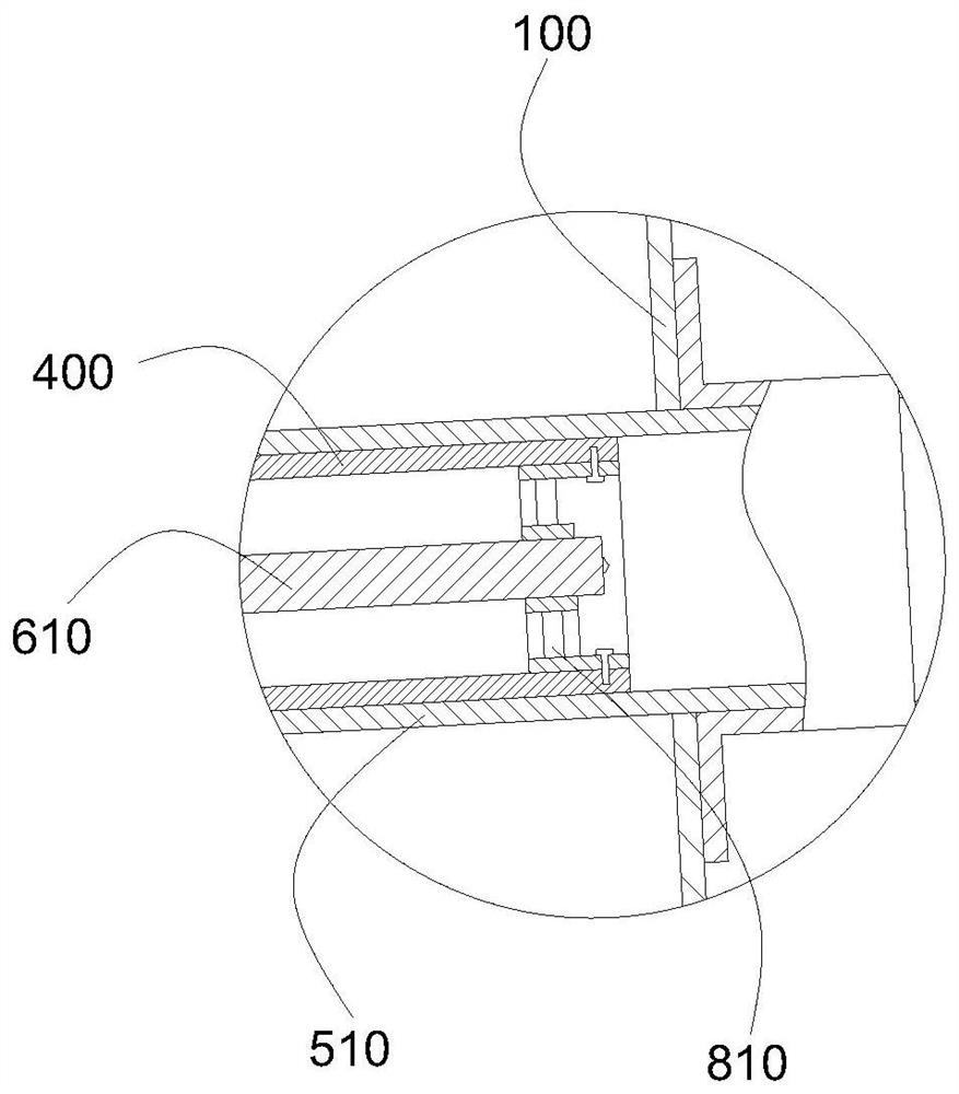
[0025] like figure 1 As shown, a specific embodiment of the present invention discloses an aeration device for treating domestic sewage, including a water tank 100, a hot air blower 200, and a driving structure 300; The air pipe 400 is inclined and inclined downward toward the side of the discharge pipe 110 of the water tank 100. A solenoid valve is installed on the discharge pipe, and the aeration pipe is inclined, so that the impurities entering the aeration pipe can be inclined to the bottom direction as much as possible. Move closer to reduce the impact of the blockage range, and also facilitate external discharge; the higher end of the inclination protrudes from the outside of the water tank 100, and both are communicated with the confluence pipe 500, and the confluence pipe 500 is communicated with the air...


PUM


Abstract

The invention provides an aeration device for treating domestic sewage. The aeration device comprises a water tank, an air heater and a driving structure, a plurality of aeration pipes are erected at the bottom of the water tank, the aeration pipes are obliquely arranged and incline downwards towards one side of a discharge pipe of the water tank, the other ends of the aeration pipes protrude out of the water tank and are all communicated with a collecting pipe, and the collecting pipe is communicated with an air outlet of an air heater; a plurality of air outlet holes are formed in the aeration pipes, cleaning structures are mounted in the aeration pipes, one ends of the cleaning structures protrude out of the inclined bottom ends of the aeration pipes and are in transmission connection with a driving structure, and the driving structure drives the cleaning structures in the aeration pipes to move, so that the air outlet holes of the aeration pipes are cleaned, and anti-blocking is realized; a relatively appropriate temperature can be provided for microorganisms in sewage by adopting a hot air supply effect, so that the activity is improved, and the reaction is accelerated; moreover, the air outlet holes can be prevented from being blocked, impurities are prevented from remaining in the aeration pipe, smooth ventilation and air outlet are maintained, and the aeration efficiency is improved.

Description

technical field [0001] The invention relates to the field of aeration devices, and more particularly, to an aeration device for treating domestic sewage. Background technique [0002] In the process of sewage treatment, air is forced into the sewage for aeration, so that the sewage in the pool is contacted with the air for oxygenation, and the liquid is stirred to accelerate the transfer of oxygen in the air to the liquid, and strengthen the organic matter in the pool, microorganisms and dissolved oxygen. Contact, oxidative decomposition of organic matter in sewage; in winter or in northern regions, due to the cold climate, the microbial activity is not high, resulting in a decrease in the reaction rate; [0003] In addition, due to the inclusion of a large amount of suspended solids in the sewage, there will even be a lot of sediment, and most of the aeration pipes are located at the bottom. Even if gas is continuously supplied to the inside of the aeration pipes, it is ine...

Claims


Application Information

Patent Timeline
Patent Type & Authority Applications(China)
IPC IPC(8): C02F7/00C02F3/34
CPCC02F7/00C02F3/34C02F2301/106C02F2303/14
Inventor 潘尚鹏蔡岳玮潘金芳
Owner 清远市德晟嘉恒能源环保工程有限责任公司
Learn More