Water conservancy ecological engineering desilting device

A technology of ecological engineering and dredging equipment, applied in the direction of heat generated by non-combustion exothermic chemical reactions, lighting and heating equipment, mechanically driven excavators/dredgers, etc., can solve river blockage and dredging equipment dredging Poor effect, affecting the normal operation of the dredging device and other problems, to achieve the effect of preventing the temperature from being too low

Active Publication Date: 2022-07-22
湘潭韶山灌区水利水电有限责任公司
View PDF6 Cites 2 Cited by
  • Summary
  • Abstract
  • Description
  • Claims
  • Application Information

AI Technical Summary

Problems solved by technology

[0002] The existing dredging device does not have a good dilution effect on the silt during use. Due to the presence of weeds in the silt, it will block the river course, affect the dredging effect, and it is inconvenient to disassemble and clean the filter screen
[0003] In view of the above problems, regarding the technical problems such as the poor dredging effect of the existing dredging device, after a large number of searches, we found an adjustable dredging device for water conservancy projects with the patent number CN202120084547.X, including the base , the top of the base is provided with a collection box, one side of the collection box is provided with a mounting plate slidingly connected with the base, the top of the mounting plate is provided with a hydraulic rod, the top of the hydraulic rod is provided with a fixed plate, and one side of the fixed plate is fixed with a dredging cylinder. A dredging motor is installed on the top of the dredging tank. The output end of the dredged motor extends to the inside of the dredged tank and is connected with a screw rod. There is a dredging pump installed on the top of the collecting tank, and a hose is installed at the suction end of the dredging pump. One end of the dredging pump is in communication with the top of the side of the dredging cylinder close to the collection box. A filter is installed inside the collection box, and the bottom of the collection box away from the dredging cylinder is provided with a sewage outlet for discharging sludge. By setting the filter It can filter the impurities in the silt, and at the same time, it is easy to disassemble and clean the filter screen. During operation, the low temperature outside will easily cause the residual water in the sewage pipe to freeze. If the ice in the sewage pipe is not cleared in time before the operation, the normal operation of the dredging device will be affected.

Method used


Image

  • Water conservancy ecological engineering desilting device
  • Water conservancy ecological engineering desilting device
  • Water conservancy ecological engineering desilting device

Examples


Embodiment 1

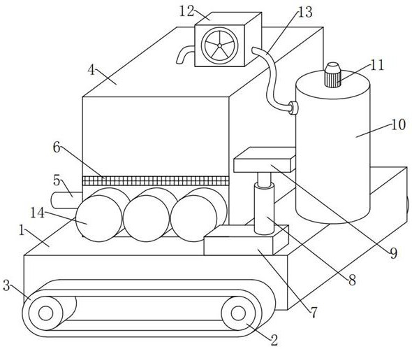
[0036] see Figure 1-2 , In the embodiment of the present invention, a water conservancy and ecological engineering dredging device, comprising:

[0037] The base 1 and the collection box 4, the front, rear and left sides of the collection box 4 are fixedly installed with several anti-overcooling components 14 which can prevent the surface temperature of the collection box 4 from being too low. The component 14 includes: a housing 15, a movable component 16 that can move autonomously in cold conditions, and a heating component 17 that can generate high-temperature heat;

[0038] The anti-overcooling component 14 here can facilitate the timely movement of the movable component 16 and the flexible cooperation of the heating component 17 when the temperature outside the collection box 4 is too low to generate a high temperature in the outer casing 15, so that the surface of the collection box 4 is heated. When the temperature rises, the ice cubes in the sewage pipe 5 are melted;...

Embodiment 2

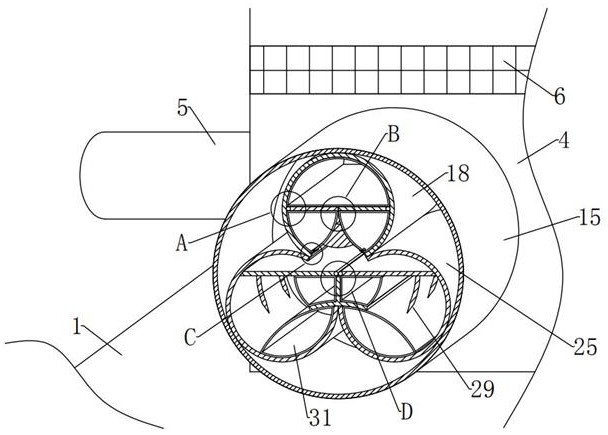
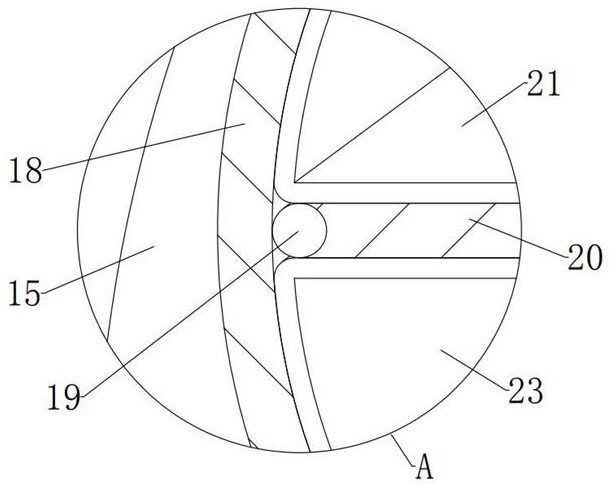
[0048] see Figure 2-5 and Figure 7-8 , Compared with Embodiment 1, the difference between the embodiment of the present invention is that the upper shell 18 is in a cylindrical shape with a hollow interior, closed front and rear, and an opening in the middle of the bottom end, and the outer surfaces of the front and rear sides of the upper shell 18 are respectively fixed and installed on the outer shell 15. The top and outer walls of the upper shell 18 are fixedly installed on the top inner wall of the outer shell 15, and the distance between the left and right outer walls of the upper shell 18 from the left and right inner walls of the outer shell 15 gradually increases from top to bottom. The front and rear ends of the 19 are respectively rotatably mounted on the middle positions of the left and right ends of the front and rear inner walls of the upper shell 18. The upper turning plate 20 is in a horizontal static equilibrium state under normal conditions. Under normal ci...

Embodiment 3

[0058] see figure 2 and Figure 6-8 , Compared with Embodiment 1, the difference between the embodiment of the present invention is that the lower shell 25 is in the shape of an inverted claw that is hollow inside, closed in the front and rear, symmetrical and convex on a longitudinal section, and the top middle of the lower shell 25 is provided with Up and down through the entrance, the entrance of the lower shell 25 and the bottom end opening of the upper shell 18 butt joints, the lower outer walls of the left and right sides of the lower shell 25 and the lower end surfaces of the left and right inner walls of the outer shell 15 fit;

[0059] The lower shell 25 here is for the convenience of accommodating the remaining heating components 17 and for limiting and supporting the lower airbag 30 and the auxiliary airbag 31 .

[0060]In the embodiment of the present invention, the limiting plate 26 is in the shape of a left-right symmetrical inverted letter “T” on a longitudina...


PUM


Abstract

The invention provides a water conservancy ecological engineering desilting device which comprises a base and a collecting box, and a plurality of anti-supercooling assemblies capable of preventing the surface temperature of the collecting box from being too low are fixedly installed at the lower ends of the outer surfaces of the front side, the rear side and the left side of the collecting box in an equally adjacent mode. The anti-supercooling assembly comprises a shell, a moving assembly capable of automatically moving under the cold condition and a heating assembly capable of generating high-temperature heat. A plurality of shells are fixedly installed at the lower ends of the outer surfaces of the front side, the rear side and the left side of the collecting box in an equally adjacent mode, each shell is in a hollow and totally-closed cylindrical shape, and the shells are made of copper. According to the desilting device for the water conservancy ecological engineering, the effect that the collecting box has an anti-supercooling function can be achieved, even if the desilting device works in cold weather in winter, residual water in the blow-off pipe is not prone to icing due to the outdoor low temperature, ice blocks in the blow-off pipe can be dredged in time before operation, and normal operation of the desilting device is guaranteed.

Description

technical field [0001] The invention relates to the technical field of water conservancy engineering, and more particularly, to a dredging device for water conservancy and ecological engineering. Background technique [0002] The existing dredging device has poor dilution effect on the silt during use, and the presence of weeds in the silt will cause blockage of the river, affecting the dredging effect, and it is inconvenient to disassemble and clean the filter screen. [0003] In view of the above problems, regarding the technical problems such as the poor dredging effect of the existing dredging devices, after a lot of searches, we found an adjustable dredging device for water conservancy projects with the patent number of CN202120084547.X, including the base The top of the base is provided with a collection box, one side of the collection box is provided with a mounting plate that is slidably connected to the base, the top of the mounting plate is provided with a hydrauli...

Claims


Application Information

Patent Timeline
Patent Type & Authority Applications(China)
IPC IPC(8): E02F3/88E02F5/28F24V30/00
CPCE02F3/88E02F5/28F24V30/00
Inventor 柏婷婷
Owner 湘潭韶山灌区水利水电有限责任公司
Why Eureka
Try Eureka