Chip clock source detection circuit and chip clock circuit based on same

A detection circuit and chip technology, which is applied in the direction of generating/distributing signals, can solve the problems of chip cost increase and consumption, and achieve the effect of reducing production cost and chip pins

Pending Publication Date: 2022-07-22
合肥甘尧电子科技有限公司
View PDF0 Cites 2 Cited by
  • Summary
  • Abstract
  • Description
  • Claims
  • Application Information

AI Technical Summary

Problems solved by technology

[0007] Aiming at the problem that the existing chip clock source selection method consumes 3 pins and increases the cost of the chip, the present invention provides a chip clock source detection circuit, which realizes chip clock source selection through 2 pins

Method used


Image

  • Chip clock source detection circuit and chip clock circuit based on same
  • Chip clock source detection circuit and chip clock circuit based on same
  • Chip clock source detection circuit and chip clock circuit based on same

Examples


Embodiment 1

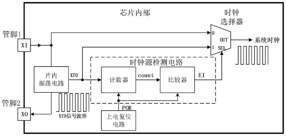
[0024] A chip clock source detection circuit, such as image 3 As shown, it includes a counter and a comparator, the input end of the counter is connected to the output end of the on-chip oscillator circuit, the output end is connected to the input end of the comparator, and the output end of the comparator is connected to the selection end of the clock selector. In this embodiment, the counter adopts a decimal counter, and the hardware circuit is a mature technology in the industry, and the implementation methods are various, for example, it is realized by a JK flip-flop, and it is realized by a chip 74LS161.

[0025] The on-chip oscillator circuit outputs an XTO pulse to the counter. Every time an XTO pulse occurs, the count value count of the counter increases by 1, and stops counting when the count value is accumulated to a preset value.

[0026] The comparator compares the count value count with a preset value, and if the count value count ≥ the preset value, outputs a hi...


PUM


Abstract

The invention discloses a chip clock source detection circuit which comprises a counter and a comparator, the input end of the counter is connected with the output end of an on-chip oscillation circuit, the output end of the counter is connected with the input end of the comparator, and the output end of the comparator is connected with the selection end of a clock selector; the on-chip oscillation circuit outputs XTO pulses to the counter, 1 is added to the count value of the counter every time one XTO pulse appears, and counting is stopped when the count value is accumulated to a preset value; the comparator compares the count value with a preset value, if the count value is larger than or equal to the preset value, a high level is output, and otherwise, a low level is output. The chip clock source detection circuit provided by the invention is only composed of a small-scale counter and a comparator, and the hardware scale is extremely small; the chip clock source detection circuit is additionally arranged in an original chip, chip clock source selection can be achieved through two pins, the clock source mode can be accurately judged without user configuration, and generation of system clock signals is ensured.

Description

technical field [0001] The invention relates to the technical field of chip design, in particular to a chip clock source detection circuit and a chip clock circuit based thereon. Background technique [0002] The chip clock source can use the internal clock source, that is, the quartz crystal oscillator circuit inside the chip, such as figure 1 shown; an external clock source can also be used, that is, the external clock is input to the chip through the chip pins, such as figure 2 As shown, the internal and external clock sources are freely selected by the user. [0003] If the chip adopts the internal clock source mode, the quartz crystal access pin 1 (XI) and pin 2 (XO) and the on-chip oscillator circuit inside the chip form a complete clock generation circuit, which outputs the XTO periodic signal; at the same time, the user The configuration information needs to be written as 0 and sent to the selection terminal SEL of the clock selector, and the clock selector select...

Claims


Application Information

Patent Timeline
Patent Type & Authority Applications(China)
IPC IPC(8): G06F1/10
CPCG06F1/10
Inventor 付永文
Owner 合肥甘尧电子科技有限公司
Why Eureka
Try Eureka