Circuit breaker

A circuit breaker and arc extinguishing chamber technology, which is applied in the field of circuit breaker equipment, can solve the problems of large overall size of the arc extinguishing chamber, and achieve the effect of compactness, good elasticity and electrical conductivity

Pending Publication Date: 2022-07-22
PINGGAO GRP +1
View PDF1 Cites 0 Cited by
  • Summary
  • Abstract
  • Description
  • Claims
  • Application Information

AI Technical Summary

Problems solved by technology

[0004] The purpose of the present invention is to provide a circuit breaker to solve the technical problem in the prior art that when the closing resistor is used in the circuit breaker, the overall size of the arc extinguishing chamber cylinder is relatively large

Method used


Image

  • Circuit breaker
  • Circuit breaker
  • Circuit breaker

Examples


Embodiment 1

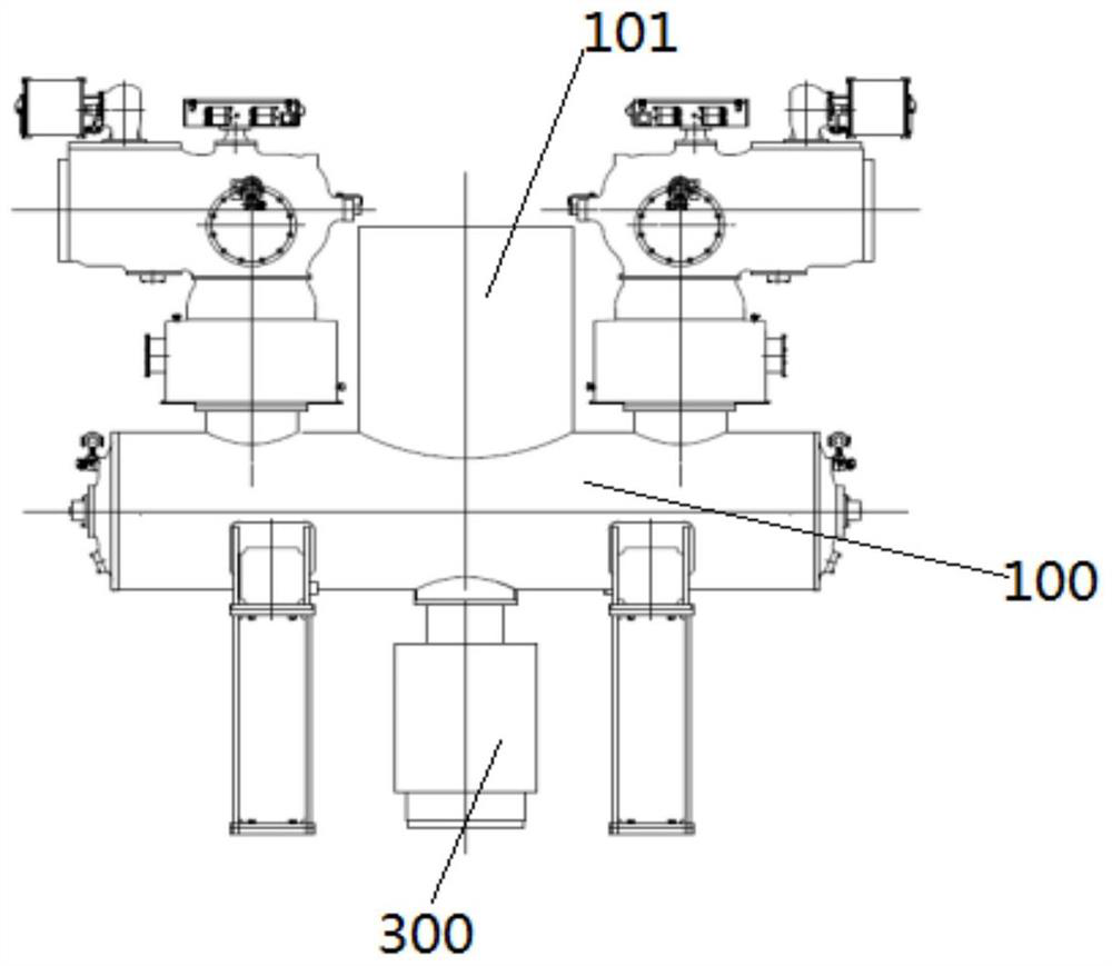
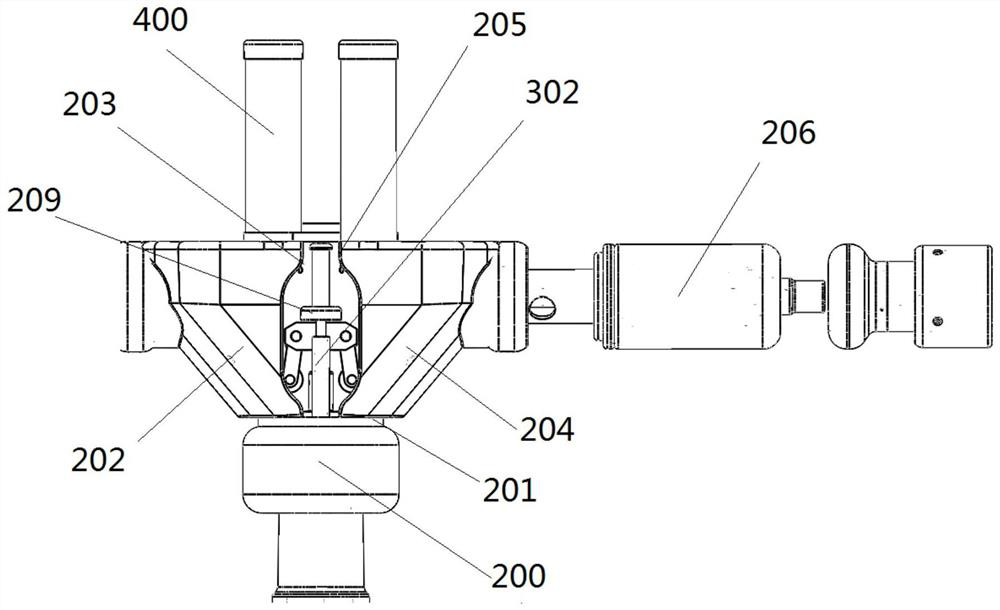
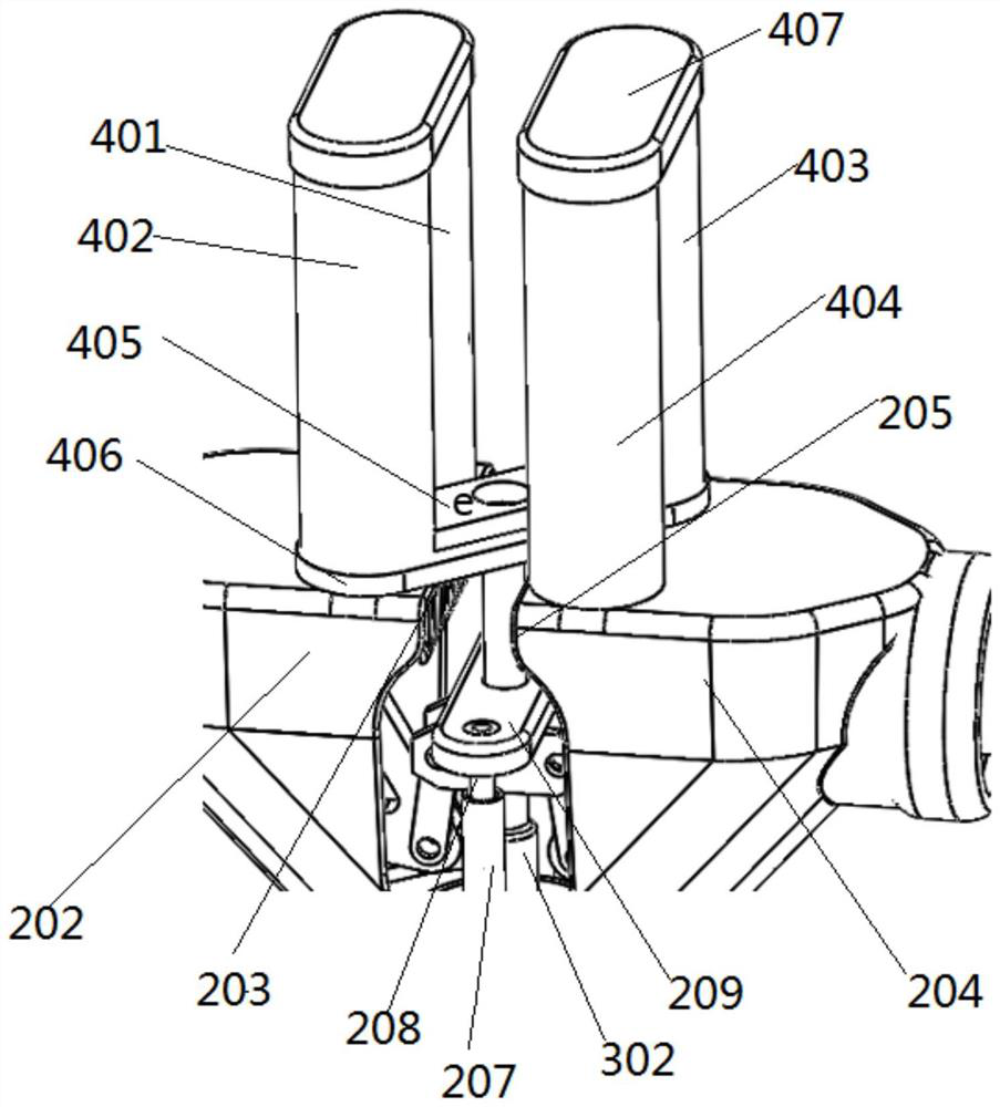
[0041] like figure 1 and figure 2 As shown, the circuit breaker provided in this embodiment is a double-break circuit breaker, and the circuit breaker includes an arc-extinguishing chamber cylinder 100 and an operating mechanism 300 , and the operating mechanism 300 includes a movable support arranged in the arc-extinguishing chamber cylinder 100 . 200 and the insulating pull rod 301, two arc extinguishing chambers are also installed in the arc extinguishing chamber cylinder 100, the two arc extinguishing chambers are supported on the movable support 200 by the support structure, and a closing resistor 400 is connected between the two arc extinguishing chambers, The arc extinguishing chamber cylinder 100 is also provided with a closing resistance static contact and a closing resistance moving contact 209, and the insulating pull rod 301 is respectively connected with the arc extinguishing chamber and the closing resistance moving contact 209 through transmission components, s...

Embodiment 2

[0056] The difference between this embodiment and Embodiment 1 is that in Embodiment 1, the reversing transmission member includes a crank arm and a connecting rod. In this embodiment, however, the reversing transmission member includes a push head, a sliding block and a reset elastic member. The push head is arranged on the driving member, the sliding block is arranged on the movable contact rod for pushing the active contact, and the sliding block is arranged on the movable contact rod for pushing the active contact. There is an inclined surface that cooperates with the ejector head, and a reset elastic member is arranged between the movable contact rod and the corresponding conductor; the following effects can be achieved. When the insulating rod goes up, the ejector head on the driving member pushes the corresponding The slider, the slider drives the corresponding movable contact rod to complete the closing of the arc extinguishing chamber. At this time, the reset elastic m...

Embodiment 3

[0058] The difference between this embodiment and Embodiment 1 is that in Embodiment 1, the resistor body extends in the up-down direction. However, in this embodiment, the extending direction of the resistor body is consistent with the extending direction of the arc extinguishing chamber cylinder.


PUM


Abstract

The invention relates to a circuit breaker which comprises an arc extinguish chamber barrel fixedly provided with an arc extinguish chamber and an operating mechanism arranged on one side of the arc extinguish chamber barrel, and a supporting structure supported on a movable support is arranged in the arc extinguish chamber barrel. The supporting structure comprises two electric conductors, the upper ends of the two electric conductors are connected through a closing resistor, and the circuit breaker comprises a closing resistor containing cavity used for covering the closing resistor. The circuit breaker further comprises a closing resistor static contact and a closing resistor moving contact, the closing resistor static contact comprises static contact split bodies arranged on the two electric conductors respectively, and the closing resistor moving contact is used for stretching into and being clamped between the two static contact split bodies so as to short-circuit the closing resistor. According to the embodiment of the invention, the arc extinguish chamber cylinder only needs to be provided with the closing resistor accommodating chamber with the corresponding size at the position, corresponding to the closing resistor, of the upper side of the arc extinguish chamber cylinder, and the overall size of the arc extinguish chamber cylinder in the radial direction and the axial direction cannot be affected.

Description

technical field [0001] The present invention relates to the technical field of circuit breaker equipment, in particular to a circuit breaker. Background technique [0002] High-voltage switchgear and GIS products are gradually developing towards compactness. In particular, power grid users have proposed standard spacing requirements. On the premise of ensuring the convenience of product operation and maintenance, it has become a trend to realize the miniaturization of high-voltage switchgear. At present, in order to prevent overvoltage during closing operation, closing resistors are generally installed on high-voltage circuit breakers to reduce the hazards of overvoltage and ensure the safe operation of the power system. In the prior art, the closing resistor is connected to the main circuit in series or in parallel. For example, the utility model patent with the authorization announcement number CN2896495Y provides a double-break tank circuit breaker arc-extinguishing chamb...

Claims


Application Information

Patent Timeline
IPC IPC(8): H01H33/02H01H33/08H01H33/42H01H9/54H01H1/50
CPCH01H33/02H01H33/08H01H33/42H01H9/54H01H1/50
Inventor 段晓辉魏建巍金玉琪谭盛武徐华王文博江经华孙清超赵树虹谢世超占小猛柴影辉高远张银穗
Owner PINGGAO GRP
Why Eureka
Try Eureka