Broadband low cross polarization microstrip patch phased-array antenna unit

A phased array antenna and microstrip patch technology, applied in antennas, antenna coupling, resonant antennas, etc., can solve the problem that the bandwidth and cross-polarization level of the microstrip patch antenna are difficult to meet the needs of the S-band radar system at the same time. problem, to optimize the impedance matching state, improve the energy coupling efficiency, and achieve the effect of high electric field polarization purity.

Pending Publication Date: 2022-07-22
中国人民解放军63660部队
View PDF0 Cites 2 Cited by
  • Summary
  • Abstract
  • Description
  • Claims
  • Application Information

AI Technical Summary

Problems solved by technology

[0007] The purpose of the present invention is to design a wideband, low cross-polarization microstrip patch phased array antenna unit working in the S-band, to solve the problem that the bandwidth and cross-polarization level of the existing microstrip patch antenna are difficult to meet the requirements of the S-band radar at the same time. Technical issues related to system usage requirements

Method used


Image

  • Broadband low cross polarization microstrip patch phased-array antenna unit
  • Broadband low cross polarization microstrip patch phased-array antenna unit
  • Broadband low cross polarization microstrip patch phased-array antenna unit

Examples


Embodiment 1

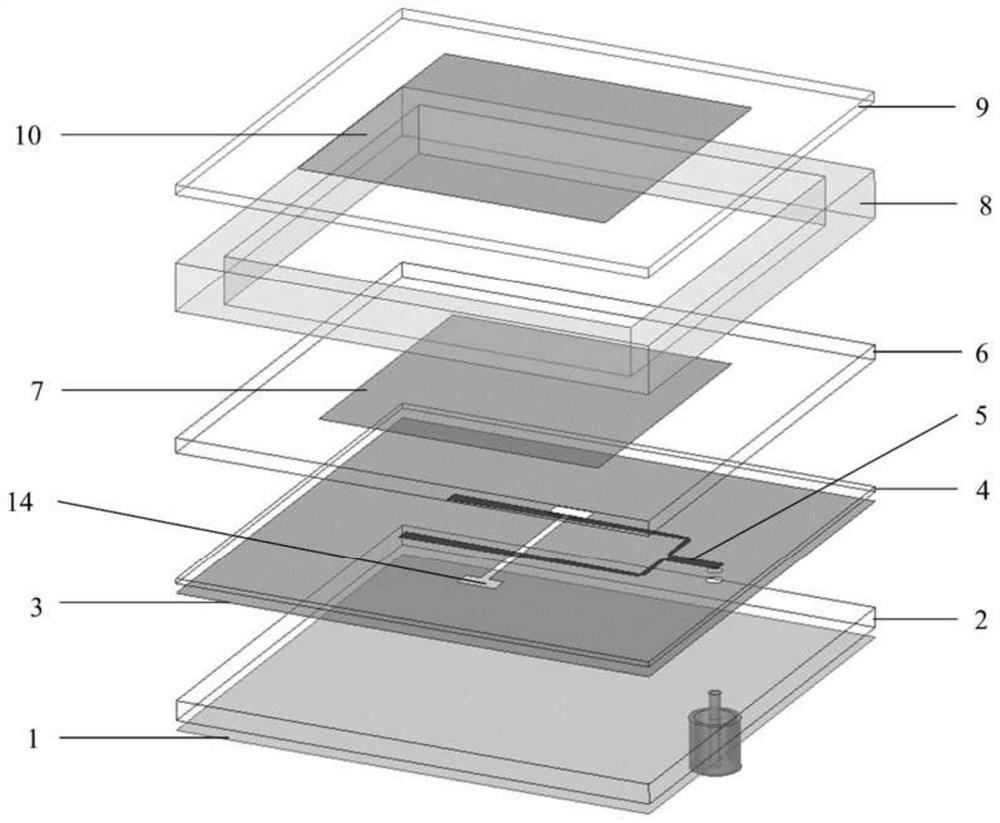
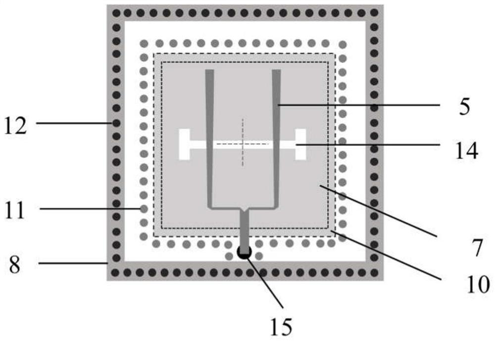
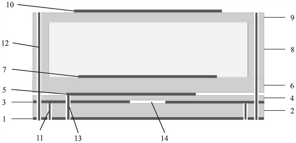
[0044] like figure 1 As shown in the figure, the main structures of the low-cross-polarization, broadband microstrip patch phased array antenna unit operating in the S-band are from bottom to top: reflection floor 1, first dielectric substrate 2, slot floor 3, second dielectric substrate 4 , microstrip line conduction strip 5, third dielectric substrate 6, square drive patch 7, fourth dielectric substrate 8, fifth dielectric substrate 9, square parasitic patch 10, metal blind hole 11 located in the first dielectric substrate 2 , the metal through holes 12 around the antenna unit, the metal blind holes 13 for feeding the feeding microstrip line, and the "H"-shaped coupling slot 14 etched on the slot floor 3 . The reflection floor 1 is laid on the lower surface of the first dielectric substrate 2, the slot floor 3 is laid on the lower surface of the second dielectric substrate 4, the microstrip line guide strip 5 is laid on the upper surface of the second dielectric substrate 4,...


PUM

PropertyMeasurementUnit
thicknessaaaaaaaaaa
lengthaaaaaaaaaa
thicknessaaaaaaaaaa

Abstract

The invention discloses a broadband low cross polarization microstrip patch phased-array antenna unit, and belongs to the technical field of microwave antennas. The antenna unit is composed of five layers of dielectric substrates, and the reflection floor is laid on the lower surface of the first dielectric substrate. The slot floor is laid on the lower surface of the second dielectric substrate, the feed microstrip line conduction band is laid on the upper surface of the second dielectric substrate, the square driving patch is laid on the upper surface of the third dielectric substrate, the square parasitic patch is laid on the upper surface of the fifth dielectric substrate, and the central area of the fourth dielectric substrate is hollowed out. The first support is used for supporting the fifth dielectric substrate; metal blind holes are formed in the periphery of the first dielectric substrate and used for connecting the reflection floor and the slot floor to form a closed metal cavity, metal through holes are designed in the periphery of the antenna unit to penetrate through all the dielectric substrates, and equivalent metal walls are formed around patches to block propagation of surface waves. According to the invention, the broadband, low-cross-polarization and wide-scanning-angle microstrip patch phased-array antenna unit with a multilayer structure can be obtained.

Description

technical field [0001] The invention belongs to the technical field of microwave antennas, and in particular relates to a broadband low-cross-polarization microstrip patch phased array antenna unit working in the S-band. Background technique [0002] With the rapid progress of electronic countermeasure technology and target detection technology, phased array radar has become the mainstream direction of current radar technology development in the past ten years. Phased array radar has the advantages of fast electronic scanning, multi-beam, beam forming, etc., and can realize multi-target detection, monitoring and tracking at the same time. In order to improve target detection ability and enhance anti-electronic interference ability, phased array radar must have low crossover polarization level. As the key front-end component of the radar system, the performance of the antenna system directly determines the performance of the radar. To reduce the cross-polarization level of t...

Claims


Application Information

Patent Timeline
Patent Type & Authority Applications(China)
IPC IPC(8): H01Q9/04H01Q1/48H01Q1/00H01Q1/52H01Q3/30H01Q21/06
CPCH01Q9/0414H01Q9/045H01Q1/48H01Q1/002H01Q1/523H01Q3/30H01Q21/065
Inventor 曹成云成真伯蒋廷勇刘启龙朱美琪王殿喜张守龙
Owner 中国人民解放军63660部队
Why Eureka
Try Eureka