
Conductive bar with high thermal conductivity and forming method thereof

A technology with high thermal conductivity and forming method, applied in circuits, electrical components, circuit/collector parts, etc., can solve the problems of affecting the service life of conductive strips, affecting the safety of electrical appliances, and burning out the connections of conductive strips. The effect of protecting conductive strips, reducing heat accumulation and avoiding burnout

Pending Publication Date: 2022-07-22
如皋市凯源电器设备有限公司
View PDF0 Cites 0 Cited by
  • Summary
  • Abstract
  • Description
  • Claims
  • Application Information

AI Technical Summary

Problems solved by technology

[0002] The conductive strip is also called the silicone rubber conductive connector. The main material is made of silicone rubber. It is composed of a layer of uncharged black silica gel and a layer of silica gel with a conductive layer. The conductive strip is more or less A certain amount of heat will be generated, especially when the resistance increases at the connection of the conductive strip, which will cause more heat to be generated at the connection of the conductive strip, and because the thermal conductivity of silicone rubber is relatively poor, the heat can only be gathered in the Around the conductive strip, it is difficult to spread outward, which will affect the service life of the conductive strip, and once the heat is too high, it will burn the connection of the conductive strip and affect the safety of electrical appliances

Method used


Image

  • Conductive bar with high thermal conductivity and forming method thereof
  • Conductive bar with high thermal conductivity and forming method thereof

Examples


Embodiment Construction

[0020] In order to deepen the understanding of the present invention, the present invention will be described in further detail below with reference to the embodiments and the accompanying drawings. The embodiments are only used to explain the present invention and do not constitute a limitation on the protection scope of the present invention.

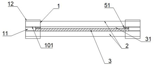
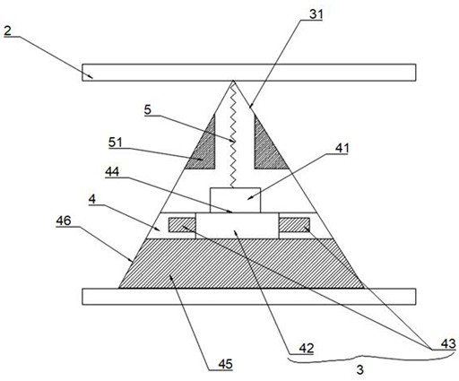
[0021] like Figure 1 to Figure 2 It is a specific embodiment of the present invention, and its structure also includes two insulating sleeve openings 1 and two silicone rubber strips 2, wherein one silicone rubber strip 2 is provided with two copper guide rails 3, and the other silicone rubber strip 2 is provided with two copper guide rails 3. There are two copper sliding grooves 31, the copper guide rail 3 is slidably arranged on the copper sliding groove 31, and a safe distance is maintained between the two silicone rubber strips 2. The interior of the insulating sleeve 1 is divided into two fixing grooves 12. The length of the cop...


PUM


Abstract

The invention discloses a high-thermal-conductivity bus bar and a forming method thereof, the high-thermal-conductivity bus bar structurally comprises two insulating sleeve openings and two silicone rubber strips, one silicone rubber strip is provided with two copper guide rails, the other silicone rubber strip is provided with two copper sliding grooves, the copper guide rails are arranged on the copper sliding grooves in a sliding mode, a safe distance is kept between the two silicone rubber strips, and the two silicone rubber strips are connected with the insulating sleeve openings. A heat conduction block is arranged in the insulation sleeve opening and enables the interior of the insulation sleeve opening to be divided into two fixing grooves, the length of the copper guide rail is equal to the length of the copper sliding groove and smaller than the length of the silicon rubber strip, and installation positions are kept between the end of the copper guide rail or the end of the copper sliding groove and the end of the silicon rubber strip. The length of the mounting position corresponds to the length of the heat conduction block, and when the end parts of the two silicon rubber strips are bonded in the fixing grooves one by one, the copper sliding grooves abut against the heat conduction block, so that the heat conduction performance of the conductive strip is improved.

Description

Technical field: [0001] The invention relates to the technical field of production of a conductive strip, in particular to a conductive strip with high thermal conductivity and a forming method thereof. Background technique: [0002] The conductive strip is also called a silicone rubber conductive connector. The main material is made of silicone rubber. It is composed of a layer of uncharged black silica gel and a layer of silica gel with a conductive layer. A certain amount of heat will be generated, especially in the case of increased resistance at the connection of the conductive strip, which will cause more heat to be generated at the connection of the conductive strip, and due to the poor thermal conductivity of silicone rubber, this heat can only be accumulated in the It is difficult to spread out around the conductive strip, which will affect the service life of the conductive strip, and once the heat is too high, it will cause the connection of the conductive strip t...

Claims


Application Information

Patent Timeline
IPC IPC(8): H01R25/14H05K7/20H01R43/00
CPCH01R25/14H05K7/2039H01R43/00
Inventor 陆新华姚峰
Owner 如皋市凯源电器设备有限公司
Learn More