Mixed type damping gap adjustable valve type magnetorheological damper

A magnetorheological damper, hybrid technology, applied in shock absorbers, shock absorbers, springs/shock absorbers, etc., can solve the problems of increasing structural stroke, small effective damping channel length, and difficult installation, etc. The effect of increasing the amplitude modulation range, increasing the effective damping channel length, and increasing the output

Pending Publication Date: 2022-07-26
GUANGXI UNIVERSITY OF TECHNOLOGY
0 Cites 0 Cited by

AI-Extracted Technical Summary

Problems solved by technology

[0003] In the traditional valve-type magneto-rheological damper, the liquid flow channel in the valve is mostly linear, which results in a small effective damping channel length, so that the output damping force is small
However, the existing valve-type magneto-rheological dampers change the shape of the damping channel. Compare...

Abstract

The invention aims to provide a hybrid damping clearance adjustable valve type magnetorheological damper. The hybrid damping clearance adjustable valve type magnetorheological damper comprises a piston rod, a left end cover, a cylinder body, a first piston head, a coil and a second piston head, a first piston head, a second piston head and a circular ring groove combination are arranged in the cylinder body to form an embedded stepped damping channel, so that the effective length of the damping channel is increased, and the output of damping force is increased; the elastic connecting piece connected with the interior of the piston head is pressed, the size of the gap of the liquid flow channel can be changed, namely the damping force is changed, and the adjustable range of the damping force is enlarged. The mixed type damping gap adjustable valve type magnetorheological damper can overcome the defects that a magnetorheological damping device in the prior art is narrow in amplitude modulation range and small in output damping force, and has the advantages of being easy to operate, large in amplitude modulation range and large in output damping force.

Application Domain

SpringsNon-rotating vibration suppression +1

Technology Topic

PhysicsEngineering +6

Image

  • Mixed type damping gap adjustable valve type magnetorheological damper
  • Mixed type damping gap adjustable valve type magnetorheological damper
  • Mixed type damping gap adjustable valve type magnetorheological damper

Examples

  • Experimental program(1)

Example Embodiment

[0032] Example 1
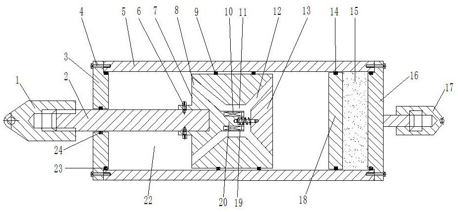
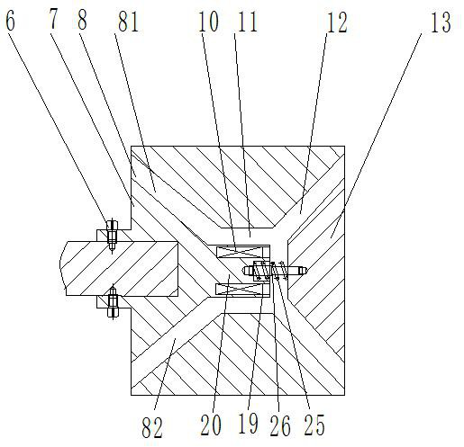
[0033] like Figure 1-5 As shown, the hybrid damping gap adjustable valve magnetorheological damper includes a piston rod 2, a left end cover 3, a cylinder block 5, a first piston head 7, a coil 10, and a second piston head 13;
[0034] The cylinder body 5 is filled with magnetorheological fluid 22, the right end of the piston rod 2 enters the cylinder body 5 through the piston rod hole on the left end cover 3, and can slide relative to the piston rod hole; the right end of the piston rod 3 It is fixedly connected with the first piston head 7 through the screw II6;
[0035] The rear end surface of the first piston head is provided with a circular truncated groove 11, the second piston head 13 is a truncated truncated body structure, and the second piston head 13 is connected to the inner part of the circular truncated groove 11 of the first piston head 7 through an elastic connecting piece. The top surface is connected, the circular table surface of the second piston head 13 corresponds to the inner circular table surface of the circular table groove 11, and a damping gap 12 is left;
[0036] An annular groove 19 is arranged on the inner top surface of the circular truncated groove 11 , a coil slot 21 is arranged in the cylinder 20 wrapped by the annular groove 19 , and the coil 10 is arranged in the coil slot 21 . And sealed by magnetic conductive material;
[0037] The first piston head is provided with a liquid flow channel 8, one end of the liquid flow channel 8 is open on the left end face of the first piston head 7, and the other end is opened to communicate with the annular groove 19; The ring groove 19 communicates the inner space of the cylinder 5 on both sides of the first piston head 7 ;
[0038] The liquid flow channel 8 includes a diagonal flow channel a81 and a diagonal flow channel b82. The left end openings of the diagonal flow channel a81 and the diagonal flow channel b82 are respectively located on the outer circumference of the left end face of the first piston head 7. The diagonal flow channel a81, the right end opening of the oblique flow channel b82 extends obliquely to the right and communicates with the left end surface of the annular groove 19.
[0039] The outer circular surface of the first piston head 7 is provided with a sealing ring groove a, in which an O-shaped sealing ring I9 is ​​provided.
[0040] It also includes a right end cover 16, the cylinder block 5 is fixedly connected with the left end cover 3 and the right end cover 16 by screws I4, and is sealed by an O-ring III23.
[0041] The right end surface of the right end cover 16 is provided with a right pull ring 17 .
[0042] The right side of the cylinder body 5 is provided with a floating piston 18, and the floating piston 18 is located between the second piston head 13 and the right end cover 16; the outer circular surface of the floating piston 18 is provided with a sealing ring groove b, which There is an O-ring Ⅱ14 inside.
[0043] The space between the floating piston 18 and the right end cap is filled with nitrogen gas 15 .
[0044] The inner circular surface of the piston rod hole on the left end cover 3 is provided with a sealing ring groove c, and an O-shaped sealing ring IV24 is provided therein.
[0045] The left end of the piston rod 2 is provided with a left pull ring 1 .
[0046] The elastic connector includes a spring 25 and a telescopic secondary rod 26 ; the telescopic secondary rod 26 also includes an outer tube 261 and an inner tube 262 ; the left end of the outer tube 261 is fixed to the middle of the right end surface of the cylinder 20 The inner tube 262 is nested and installed in the outer tube 261 from the left end, and the right end of the inner tube 262 is fixedly connected with the middle of the top surface of the second piston head 13; the left end of the inner tube 262 is provided with a slider 263 , the slider 263 is in sliding contact with the inner wall of the outer tube 261 , and a limit ring 264 is provided on the right port of the outer tube 261 to limit the slider 263 so that the inner tube 262 will not be separated from the outer tube 261 .

PUM

no PUM

Description & Claims & Application Information

We can also present the details of the Description, Claims and Application information to help users get a comprehensive understanding of the technical details of the patent, such as background art, summary of invention, brief description of drawings, description of embodiments, and other original content. On the other hand, users can also determine the specific scope of protection of the technology through the list of claims; as well as understand the changes in the life cycle of the technology with the presentation of the patent timeline. Login to view more.

Similar technology patents

Semiconductor laser device

ActiveUS20120147916A1small chip sizehigh output
Owner:ROHM CO LTD

Nitride semiconductor light emitting device and manufacturing method thereof

InactiveUS20130056747A1high outputincrease dope efficiency
Owner:LEE JIN SUB +4

Alkaline battery

ActiveCN103996882Ahigh outputextend your life
Owner:SHONAN CORUN ENERGY

Laser oscillator and laser processing apparatus

InactiveUS20090252184A1improvement in laser oscillation efficiencyhigh output
Owner:MIYACHI TECHNOS CORP

Classification and recommendation of technical efficacy words

  • high output

Electric tool powered by a plurality of battery packs and adapter therefor

ActiveUS20110197389A1lengthen service lifehigh output
Owner:MAKITA CORP

Basic polymer electrolyte fuel cell

InactiveUS6986962B2cost reductionhigh output
Owner:HONDA MOTOR CO LTD

Engine equipped with adjustable valve timing mechanism

ActiveUS20090031973A1high fuel efficiencyhigh output
Owner:MITSUBISHI MOTORS CORP

Gas burner apparatus and cooking apparatus including the same

ActiveUS20170108226A1high outputreduce boiling time
Owner:SAMSUNG ELECTRONICS CO LTD
Why Eureka
Try Eureka