
High-precision drilling machine for workpiece machining

一种高精度、钻床的技术,应用在金属加工设备、金属加工机械零件、制造工具等方向,能够解决加工精度不高、钻床使用不便、易高温作业等问题,达到钻孔深度精确、保证降温效率、避免高温作业的效果

Pending Publication Date: 2022-07-29
梁少龙
View PDF8 Cites 0 Cited by
  • Summary
  • Abstract
  • Description
  • Claims
  • Application Information

AI Technical Summary

Problems solved by technology

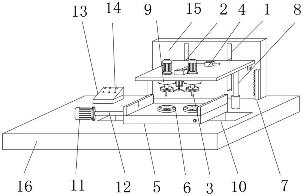
However, the following problems often exist in the existing drilling machine during use; 1. The processing accuracy of the existing drilling machine is not high, and the depth of the drilling is generally estimated according to the external length of the drill bit visually. The drilling depth cannot be accurate and the error is large; 2. The existing The processing efficiency of the drilling machine is not high, and it is inconvenient to process workpieces with different apertures and different models, resulting in a narrow application range of the drilling machine, which is not conducive to large-scale promotion and use; 3. The drill bits of the existing drilling machine are very easy to operate at high temperature during the long-term processing process , resulting in a short service life of the drilling machine and increased equipment costs; 4, when the existing drilling machine processes the workpiece, it often uses clamping parts to fix the workpiece, which not only easily damages the workpiece during the clamping process but also The clamping work is cumbersome, which makes the drilling machine inconvenient to use

Method used


Image

  • High-precision drilling machine for workpiece machining
  • High-precision drilling machine for workpiece machining
  • High-precision drilling machine for workpiece machining

Examples


Embodiment Construction

[0031] In order to make the technical means, creative features, achievement goals and effects realized by the present invention easy to understand, the present invention will be further described below with reference to the specific embodiments.

[0032] In the description of the present invention, it should be noted that the terms "upper", "lower", "inner", "outer", "front end", "rear end", "two ends", "one end" and "the other end" The orientation or positional relationship indicated by etc. is based on the orientation or positional relationship shown in the accompanying drawings, and is only for the convenience of describing the present invention and simplifying the description, rather than indicating or implying that the indicated device or element must have a specific orientation, with a specific orientation. The orientation configuration and operation are therefore not to be construed as limiting the invention. Furthermore, the terms "first" and "second" are used for desc...


PUM


Abstract

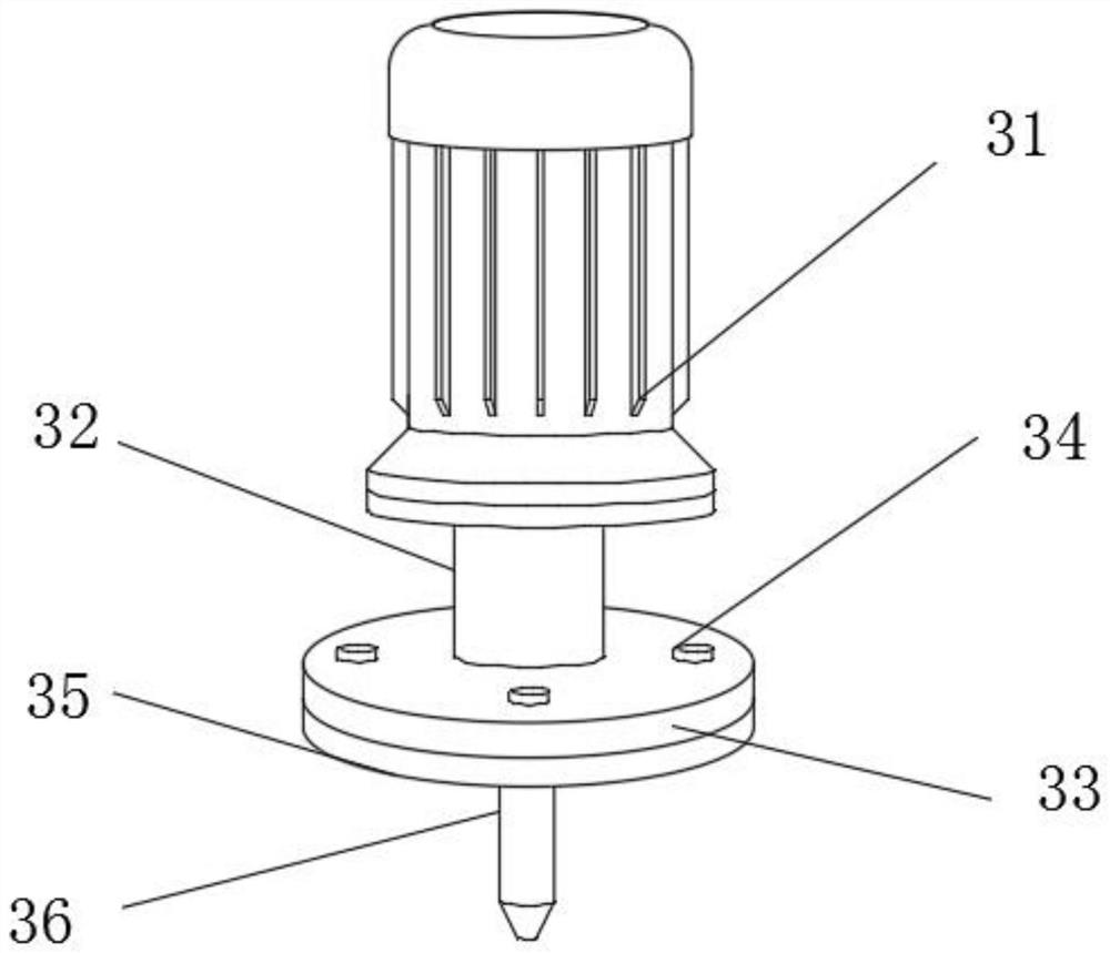
The high-precision drilling machine comprises a bottom plate, a driving part is fixedly connected to the rear portion of the upper end of the bottom plate, a cooling device and two drilling devices penetrate through the front portion of the driving part, an executing part is fixedly installed at the upper end of the bottom plate, and a second sliding groove is formed in the middle of the upper end of the bottom plate; a first air cylinder is fixedly mounted on the left portion of the upper end of the bottom plate, a first push rod is fixedly mounted at the output end of the first air cylinder, a mounting part is fixedly connected to the right end of the first push rod, two machining tables are fixedly mounted in the middle of the mounting part, and a numerical control table is fixedly mounted on the rear portion of the upper end of the bottom plate. According to the high-precision drilling machine for workpiece machining, drilling machining of different depths can be achieved, and the drilling depth is accurate; different hole diameters and different types of workpieces can be machined, and the application range of the drilling machine is widened; the cooling device can avoid high-temperature operation of the drill bit; in addition, the drilling machine is fixed through the negative pressure effect, and fixing operation is more convenient.

Description

technical field [0001] The invention relates to the technical field of drilling machines, in particular to a high-precision drilling machine used for machining workpieces. Background technique [0002] A bed refers to a machine tool that mainly uses a drill to machine holes in a workpiece. Usually the rotation of the drill bit is the main movement, and the axial movement of the drill bit is the feed movement. However, the existing drilling machines often have the following problems in the use process: 1. The existing drilling machines have low processing accuracy, and the depth of the drilling is generally estimated according to the external length of the drill bit, so the drilling depth cannot be accurate, and the error is large; 2. The existing drilling The processing efficiency of the drilling machine is not high, and it is inconvenient to process the workpiece with different apertures and models, resulting in a narrow application range of the drilling machine, which is ...

Claims


Application Information

Patent Timeline
Patent Type & Authority Applications(China)
IPC IPC(8): B23B39/16B23Q3/08B23Q3/12B23Q11/10B23Q17/20B23Q17/24
CPCB23Q3/088B23Q11/10B23B39/161B23Q17/2471B23Q17/20B23Q3/12Y02P70/10
Inventor 梁少龙
Owner 梁少龙
Learn More