Novel fishplate grinding equipment

A fishplate and equipment technology, applied in grinding/polishing equipment, metal processing equipment, grinding machines, etc., can solve problems such as difficult manual handling, explosion, and complicated hoisting equipment, so as to facilitate monitoring of pressure conditions, ensure processing environment, reduce The effect of post-maintenance

Pending Publication Date: 2022-07-29
华德澳铁路技术(苏州)有限公司
View PDF0 Cites 0 Cited by
  • Summary
  • Abstract
  • Description
  • Claims
  • Application Information

AI Technical Summary

Problems solved by technology

[0002] The fish plate, commonly known as the splint, plays a connecting role at the joint of the track. It is a connecting fastener used for the connection between the track and the track. It usually uses a blank plate, and each part of the blank plate is processed according to a certain processing sequence. The side surface is processed by turning, grinding and other processes. Manual grinding is uneven, with burrs, low efficiency, and difficult to guarantee product quality. There are also some grinding equipment on the market, but the fishplate needs to be polished with many contours, and a single grinding equipment needs to be continuously debugged and polished. location, the grinding time is long, it is difficult to meet the grinding requirements, the same grinding equipment will wear out due to long-term grinding, it is difficult to adjust, and the re-adjustment is complicated. high, large
[0003] In addition, a large amount of waste chips are generated during the grinding process. The waste chips are splashed under the drive of the high-speed grinding wheel, which is easy to accidentally injure the operator. The operating environment is poor. The grinding process is often accompanied by sparks. Sparks collide with dusty waste chips, which is easy to ignite the dust and cause an explosion. , the existing grinding equipment has potential safety hazards

Method used


Image

  • Novel fishplate grinding equipment
  • Novel fishplate grinding equipment
  • Novel fishplate grinding equipment

Examples


Embodiment Construction

[0022] The preferred embodiments of the present invention will be described in detail below with reference to the accompanying drawings, so that the advantages and features of the present invention can be more easily understood by those skilled in the art, and the protection scope of the present invention can be more clearly defined.

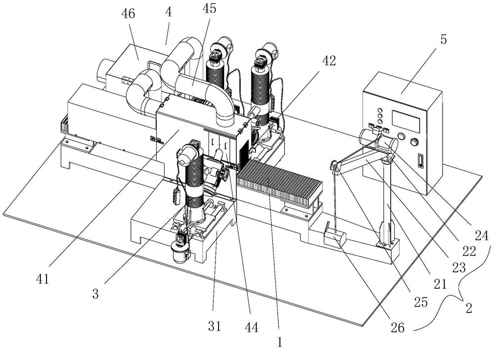
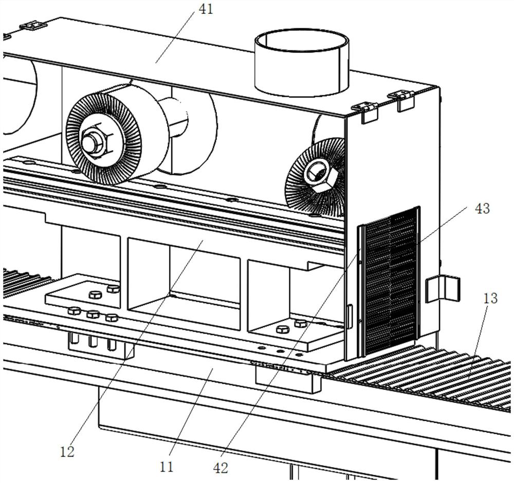
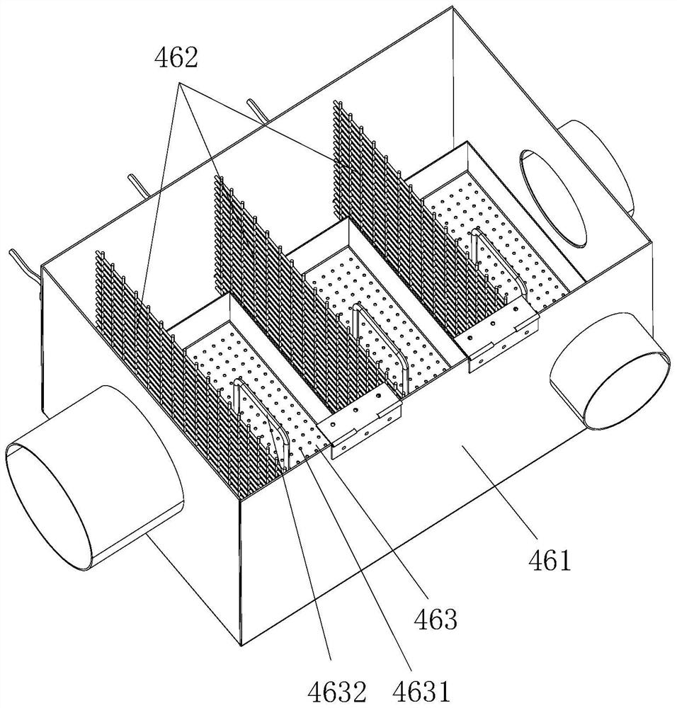
[0023] see Figure 1 to Figure 4 , the embodiments of the present invention include:

[0024] A new type of fishplate grinding equipment, the new type of fishplate grinding equipment includes a fishplate positioning and conveying mechanism 1, a hoisting device 2, a grinding device 3, a waste collection and processing device 4 and a control cabinet 5. The fishplate positioning The conveying mechanism 1 includes a single-axis driver 11, a fishplate positioning tool 12 and an organ cover 13. The single-axis driver 11 drives the fishplate positioning tool 12 to move horizontally, and the bottom plate of the fishplate positioning tool 12 and the two ...


PUM


Abstract

The novel fishplate polishing equipment comprises a fishplate positioning and conveying mechanism, a hoisting device, a polishing device, a waste collecting and processing device and a control cabinet, the fishplate positioning and conveying mechanism comprises a single-shaft driver, a fishplate positioning tool and an organ cover, and the single-shaft driver drives the fishplate positioning tool to move horizontally; the fishplate positioning tool bottom plate is connected with the two ends of the single-shaft driver through organ covers correspondingly, the input end of the single-shaft driver is in butt joint with a hoisting device, and the two sides of the fishplate positioning conveying mechanism are provided with three-station grinding devices for grinding the contours of the two sides and the top face of a fishplate correspondingly. The single-shaft driver is sleeved with a collecting box of the waste collecting and processing device, and a control cabinet is further arranged at the side end of the fishplate positioning and conveying mechanism. In this way, scrap iron dust and sparks generated in the polishing process can be automatically collected and treated, explosion is avoided, a fishplate can be conveniently hoisted, and the polishing angle and position can be adjusted.

Description

technical field [0001] The invention relates to the technical field of fishplate processing, in particular to a new type of fishplate grinding equipment. Background technique [0002] The fish plate, commonly known as the splint, plays a connecting role at the rail joint. It is a connecting fastener used for the connection between the rail and the rail. It usually uses a blank plate. The side is processed by turning, grinding and other processes. Manual grinding is uneven, has burrs, low efficiency, and it is difficult to ensure product quality. There are also some grinding equipment on the market, but the fishplate needs to be polished with many contours, and a single grinding equipment needs to be continuously adjusted and polished. Position, grinding time is long, it is difficult to meet the grinding requirements, the grinding wheel will be worn out due to the long grinding time of the same grinding equipment, it is difficult to adjust, and the re-commissioning is complic...

Claims


Application Information

Patent Timeline
IPC IPC(8): B24B9/04B24B27/00B24B41/00B24B41/06B24B55/06B24B55/12
CPCB24B9/04B24B27/0023B24B27/0069B24B41/005B24B41/06B24B55/06B24B27/0076B24B55/12
Inventor 孙中华易际忠付盛
Owner 华德澳铁路技术(苏州)有限公司
Why Eureka
Try Eureka