
Mobile operation mechanical arm tail end force application control method and system

A mobile operation and control method technology, applied in the direction of manipulators, program-controlled manipulators, manufacturing tools, etc., can solve the problems of no consideration of force application capacity/operability, no consideration of inherent differences, and many degrees of freedom, so as to achieve improvement. Operability, avoiding instability, and improving the effect of exerting force

Pending Publication Date: 2022-07-29
SHANDONG UNIV
View PDF5 Cites 2 Cited by
  • Summary
  • Abstract
  • Description
  • Claims
  • Application Information

AI Technical Summary

Problems solved by technology

[0003] But this integration of the chassis and the robotic arm also brings new difficulties
First, the model of the mobile chassis and manipulator is different from the interactive environment. The chassis is usually in an unstructured environment with complex dynamics, while the manipulator is usually in a free-contact environment. Second, due to the combination of the chassis and the manipulator, the mobile The robotic arm is actually a kinematic redundant system, which will cause more degrees of freedom in the redundant system than are required to perform the task, increasing the requirements for control
[0004] The inventors found that most of the current research regards the chassis as an additional mechanism of the manipulator, without considering the inherent differences between them in terms of dynamics and interaction environments; since the positioning accuracy of the mobile chassis is usually low, such methods lead to mechanical problems. The tracking error at the end of the arm is relatively large; most of the research on improving control accuracy is carried out in the context of dynamic control, using complex control strategies, it is difficult to ensure the stability of the system; in addition to trajectory planning, mobile manipulators are often used to deal with high Load tasks, in which moving the manipulator must exert a large force on its environment, and the current research is only carried out in the null space for the force control of the end of the manipulator, without considering any optimization in Cartesian space and Get Better Force Ability / Maneuverability

Method used


Image

  • Mobile operation mechanical arm tail end force application control method and system
  • Mobile operation mechanical arm tail end force application control method and system
  • Mobile operation mechanical arm tail end force application control method and system

Examples


Embodiment 1

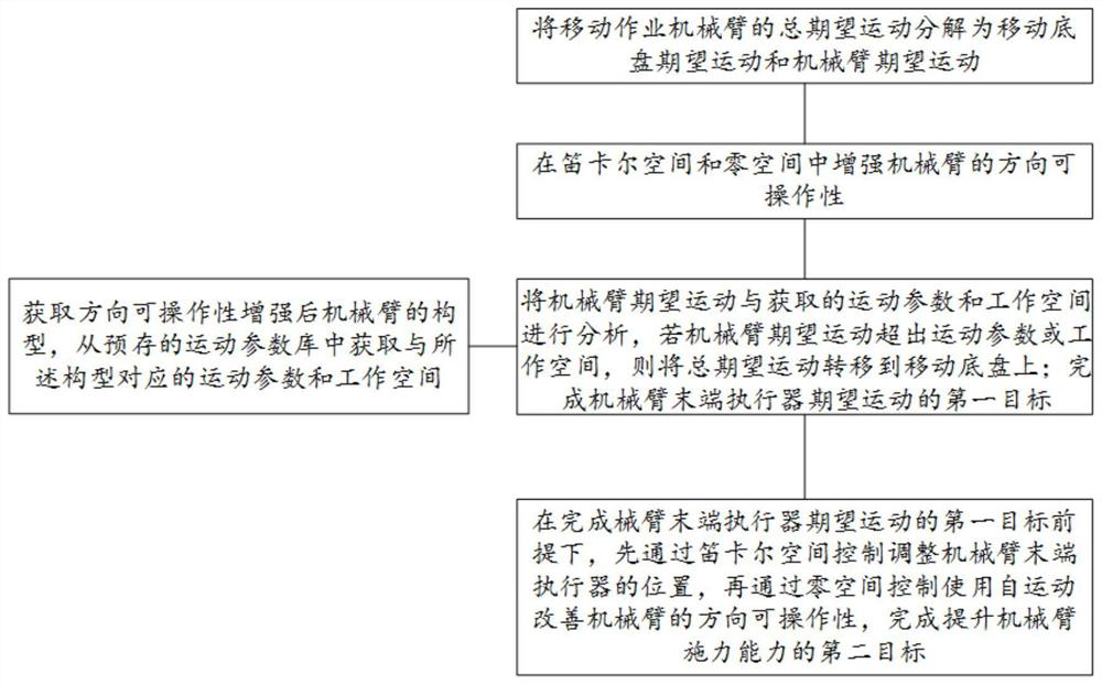
[0043] like figure 1 As shown, the present invention provides a method for controlling the end force application of a mobile working manipulator, including:

[0044] S1. Decompose the total desired motion of the mobile working manipulator into the desired motion of the mobile chassis and the desired motion of the manipulator through a weighted matrix;

[0045]The total desired motion of the mobile working manipulator can be understood as the desired motion of the mobile manipulator system during the moving work, which may include desired speed and desired trajectory, etc. The mobile manipulator system may include a mobile chassis and a manipulator; this implementation For example, the total desired motion of the mobile working manipulator can be set as the desired mobile manipulator system speed, including the manipulator joint speed and the Cartesian speed of the mobile chassis.

[0046] S2. Enhance the directional maneuverability of the robotic arm in Cartesian space and nu...

Embodiment 2

[0084] This embodiment provides a force application control system for the end of a mobile working manipulator, including:

[0085] A desired decomposition module, configured to: decompose the total desired motion of the mobile working manipulator into the desired motion of the moving chassis and the desired motion of the manipulator;

[0086] The workspace determination module is configured to: obtain the configuration of the manipulator, and obtain the motion parameters and workspace corresponding to the configuration from the pre-stored motion parameter library;

[0087] The first control target control module is configured to: if the desired motion of the manipulator exceeds the motion parameters or the working space, transfer the total desired motion to the mobile chassis to complete the first control goal of controlling the desired motion of the end effector of the manipulator;

[0088]The second control target control module is configured to: under the premise of comple...

Embodiment 3

[0091] This embodiment provides an electronic device, including a memory, a processor, and a computer program stored in the memory and running on the processor, the processor implements the mobile operation described in Embodiment 1 when the processor executes the program The steps in the method of controlling the force applied at the end of the manipulator.


PUM


Abstract

The invention belongs to the technical field of robot control, and provides a mobile operation mechanical arm tail end force application control method and system. The total expected motion trail of a mobile operation mechanical arm is decomposed into a mobile chassis expected motion trail and a mechanical arm expected motion trail; whether the expected movement is transferred to the movable chassis to be controlled or not is judged by comparing the expected movement with a preset working space in a movement track parameter library, and the interaction condition of the movable chassis and the mechanical arm is considered; meanwhile, on the premise that a first control target of expected movement of the end effector of the mechanical arm is completed, the position of the end effector of the mechanical arm is controlled and adjusted through a Cartesian space, then the direction of the mechanical arm is controlled through a null space, the direction operability of the mechanical arm is improved, and a second control target of the force application capacity of the mechanical arm is completed; the force application capacity of the tail end of the mechanical arm is improved, and the tracking precision of the tail end of the mechanical arm is improved.

Description

technical field [0001] The invention belongs to the technical field of robot control, and in particular relates to a method and a system for controlling the force exerted by the end of a mobile working manipulator. Background technique [0002] Mobile manipulators have flexible maneuverability and good operational performance, and have been used in many application fields, including household services, special disaster relief, and logistics and distribution. The integration of the mobile chassis of the mobile manipulator and the six-degree-of-freedom manipulator can effectively improve its working space and provide it with more degrees of freedom. [0003] But the integration of this chassis with the robotic arm also brings new difficulties. First, the model and interactive environment of the mobile chassis and the manipulator are different. The chassis is usually in an unstructured environment with complex dynamics, while the manipulator is usually in a free contact enviro...

Claims


Application Information

Patent Timeline
Patent Type & Authority Applications(China)
IPC IPC(8): B25J9/16
CPCB25J9/1664B25J9/1615
Inventor 宋锐于浩川王艳红刘义祥付天宇郑玉坤
Owner SHANDONG UNIV
Learn More