Automobile kinetic energy recovery system and working method thereof

A kinetic energy recovery system and vehicle system technology, applied in the field of automobile kinetic energy recovery, can solve the problems of unsolved vehicle power source, unable to fully utilize vehicles, unable to realize road utilization, etc., to achieve braking control speed, improve Utilization rate, the effect of maintaining stable operation

Pending Publication Date: 2022-07-29
吉林省万能工二十四小时在线科技有限公司
View PDF1 Cites 0 Cited by
  • Summary
  • Abstract
  • Description
  • Claims
  • Application Information

AI Technical Summary

Problems solved by technology
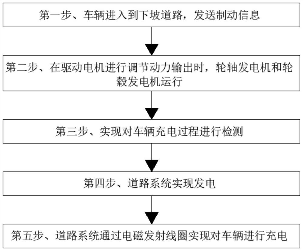
Although some road sections have emergency avoidance lanes, it still cannot solve the risks and huge losses caused by the loss of control of trucks on downhill sections. The inertia and gravity generated by the downhill are used to generate electricity to save resources. However, there are still various problems in the kinetic energy recovery of various vehicles on the market.
[0003] For example, the authorized announcement number is CN102022291A The disclosed highway downhill driving inertia power generation system, although it has realized the use of the inertial force of highway downhill driving, through the change of closed coil magnetic flux to generate power for the electric field, and because the vehicle magnetic pole Under the action of electromagnetic force, it can increase the downhill resistance of driving and reduce the wear and tear of automobile brakes. However, it does not solve the problem of the existing vehicle power source, cannot realize power generation, cannot fully utilize the consumption of the vehicle's own kinetic energy, and realize kinetic energy utilization. And the problem that it is impossible to realize the utilization of the road, make full use of the characteristics of the vehicle under gravity and inertia, and perform power generation and charging. Therefore, we propose a vehicle kinetic energy recovery system and its working method

Method used


Image

  • Automobile kinetic energy recovery system and working method thereof
  • Automobile kinetic energy recovery system and working method thereof

Examples


Embodiment Construction

[0025] The technical solutions in the embodiments of the present invention will be clearly and completely described below with reference to the accompanying drawings in the embodiments of the present invention. Obviously, the described embodiments are only a part of the embodiments of the present invention, but not all of the embodiments. Based on the embodiments of the present invention, all other embodiments obtained by those of ordinary skill in the art without creative efforts shall fall within the protection scope of the present invention.

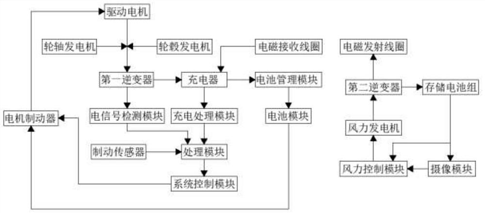
[0026] see figure 1 , the present invention provides a technical solution: an automobile kinetic energy recovery system, including a vehicle system and a road system, the vehicle system includes a system control module, and the system control module is used to realize effective control and adjustment of the vehicle system , and realize the calculation and processing of parameters, the system control module is electrically connected wi...


PUM


Abstract

The invention discloses an automobile kinetic energy recovery system which comprises a vehicle system and a road system, the vehicle system comprises a system control module, the system control module is electrically connected with a processing module, the processing module is electrically connected with a charging processing module, the charging processing module is electrically connected with a charger, and the charger is electrically connected with a power supply. The charger is electrically connected with a first inverter, the first inverter is electrically connected with an axle generator, a hub generator and a battery management module, and the charger is further electrically connected with an electromagnetic receiving coil; the road system comprises a wind driven generator, the wind driven generator is electrically connected with a second inverter, and the second inverter is electrically connected with a storage battery pack and an electromagnetic transmitting coil. The gravity and inertia energy are utilized through the vehicle system and the road system, power generation is effectively achieved, the utilization rate is increased, the vehicle can be braked, and stable operation of the vehicle is kept.

Description

technical field [0001] The invention belongs to the technical field of automobile kinetic energy recovery, and in particular relates to an automobile kinetic energy recovery system and a working method thereof. Background technique [0002] Cars, especially heavy-duty trucks, will generate huge inertia when going downhill, and this kind of inertia is not beneficial. Some serious accidents are caused by the loss of control of trucks going downhill. Although some road sections are equipped with emergency evasion lanes, the risks and huge losses caused by loss of control of trucks on downhill sections still cannot be solved. The inertia and gravity generated by the downhill generate electricity to save resources. However, there are still various problems in the kinetic energy recovery of various vehicles on the market. [0003] For example, the inertial power generation system for highway downhill driving disclosed by the authorization announcement number CN102022291A, althoug...

Claims


Application Information

Patent Timeline
Patent Type & Authority Applications(China)
IPC IPC(8): B60L7/10H02J7/00H02J7/14H02J50/10H02K7/18F03D9/11F03D9/43
CPCB60L7/10H02K7/1846H02K7/1861H02J7/14H02J7/0047H02J50/10F03D9/11F03D9/43
Inventor 李锐
Owner 吉林省万能工二十四小时在线科技有限公司
Why Eureka
Try Eureka