Airfoil unfolding mechanism and folding wing flight device

A deployment mechanism and wing deployment technology, which is applied in the direction of wing adjustment, etc., can solve the problems of long deployment time and unreliable locking of the wing deployment mechanism, and achieve the effects of ingenious structural design, saving production cycle and cost, and fewer parts

Active Publication Date: 2022-07-29
XIAN LINGKONG ELECTRONICS TECH CO LTD
View PDF8 Cites 0 Cited by
  • Summary
  • Abstract
  • Description
  • Claims
  • Application Information

AI Technical Summary

Problems solved by technology

[0006] The purpose of the present invention is to provide a wing surface deployment mechanism, which solves the problems of long deployment time and unreliable locking after deployment of the existing wing deployment mechanism

Method used


Image

  • Airfoil unfolding mechanism and folding wing flight device
  • Airfoil unfolding mechanism and folding wing flight device
  • Airfoil unfolding mechanism and folding wing flight device

Examples


Embodiment Construction

[0027] The present invention will be described in detail below with reference to the accompanying drawings and specific embodiments.

[0028] The invention provides an airfoil unfolding mechanism:

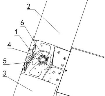
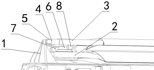
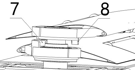
[0029] like figure 1 As shown, the airfoil deployment mechanism includes a deployment mechanism mounting seat 1 that is fixedly connected to the fuselage and two elastic sheets 4. The two elastic sheets 4 are long arc-shaped elastic sheets, and the curved surfaces where the two elastic sheets 4 are located intersect. ; The two elastic sheets 4 are fixedly connected with the mounting base 1 of the deployment mechanism, and one end of the elastic sheet 4 is an elastic limit end, such as Figure 4 As shown, tooth-shaped bosses are respectively provided on the rotating parts of the second wing 3 and the first wing 2, and the tooth-shaped bosses are arranged along the rotation direction of the wing. 2. The tooth-shaped bosses in the rotation direction are in contact with each other, a...


PUM


Abstract

The airfoil surface unfolding mechanism comprises an airfoil rotating shaft, the airfoil rotating shaft is sequentially sleeved with a first airfoil and a second airfoil, an unfolding mechanism mounting base is arranged on one side of the airfoil rotating shaft, and the first airfoil and the second airfoil are connected with the unfolding mechanism mounting base through elastic pieces; a boss is further arranged on the unfolding mechanism mounting seat, the elastic sheet can effectively prevent the second wing and the first wing from reversing after being unfolded, and the boss prevents the second wing and the first wing from being excessively unfolded, namely the second wing and the first wing are prevented from continuing to rotate after being unfolded in place; according to the folding wing flying device, the structure is simple, the number of parts is small, the weight is light, buffering parts are made of finished foamed aluminum, locking reeds are machined through spring steel wire cutting, the machining technology is simple, the material utilization rate is high, the production period can be greatly shortened, and the production cost can be greatly reduced. And the wing surface unfolding mechanism is mounted on the fuselage by utilizing the unfolding mechanism mounting seat.

Description

technical field [0001] The invention belongs to the technical field of unmanned aerial vehicle folding wing unfolding mechanism, and relates to a wing surface unfolding mechanism. [0002] The invention also relates to a folding wing flying device. Background technique [0003] In the prior art, most of the folding wing unfolding mechanisms are driven by springs, motors, steering gears, etc., and rely on gears to ensure synchronization. It is not widely used in practical applications due to its long deployment time, asynchronous deployment process, unreliable deployment after deployment, unreliable locking after deployment, easy failure in long-term storage, and complex structure. [0004] It is invented that when the folding wing unfolding mechanism adopts the gas actuator as the driving source, the unfolding time can reach less than 0.5s, and the unfolding is rapid; during storage and transportation, the wings are fixed and limited by the gas actuator, the connecting rod ...

Claims


Application Information

Patent Timeline
Patent Type & Authority Applications(China)
IPC IPC(8): B64C3/56
CPCB64C3/56B64U10/25
Inventor 张科张莹张晓攀严飞沈洋赵志孝
Owner XIAN LINGKONG ELECTRONICS TECH CO LTD
Why Eureka
Try Eureka