Touch screen production equipment and processing method thereof

A technology of production equipment and processing method, which is applied to touch screen production equipment and its processing field, can solve the problems of broken glass and weak adsorption of adsorbents, and achieves the advantages of improving production efficiency, reducing manual material reclaiming operation steps, and improving material reclaiming efficiency. Effect

Active Publication Date: 2022-07-29
ZHE JIANG CHANGXING HELI OPTOELECTRONIC TECH CO LTD
View PDF11 Cites 0 Cited by
  • Summary
  • Abstract
  • Description
  • Claims
  • Application Information

AI Technical Summary

Problems solved by technology

[0002] The mobile phone screen is also called the display screen, which is used to display images and colors. The screen size is calculated according to the diagonal of the screen, usually in inches, which refers to the length of the screen diagonal. The material of the mobile phone screen is becoming more and more important. In the production process of the mobile phone screen, the display lamp group of the realistic color needs to be attached to a piece of glass. The production of the mobile phone screen glass is made by laser cutting a large piece of glass. However, after the glass is cut, it is necessary to collect and place the glass. At present, it is not possible to effectively take and place the glass in different positions, and some production lines manually take and place the material, and then in the process of retrieving and placing the glass. In manual reclaiming, it is impossible to achieve horizontal vacuum adsorption of the vacuum reclaiming head to the glass, which leads to the problem that the adsorption stone is not firmly adsorbed. Usually, when the glass cannot be adsorbed, the staff will use a large force to adsorb, and then Easy to break the glass

Method used


Image

  • Touch screen production equipment and processing method thereof
  • Touch screen production equipment and processing method thereof
  • Touch screen production equipment and processing method thereof

Examples


Embodiment 1

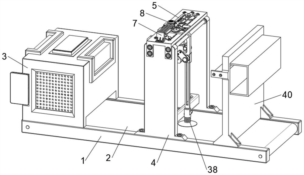
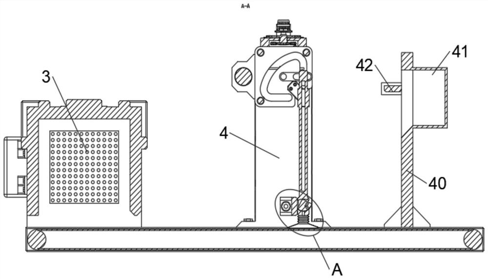
[0040] Please refer to figure 1 and Figure 10 As shown, a touch screen production equipment includes a work frame 1, the inner side of the work frame 1 is provided with a transmission device 2 for driving the screen glass, the work frame 1 is fixedly installed with a cutting device 3 for cutting the screen glass, and the transmission device 2 and The cutting device 3 is electrically connected with the equipment control device. The work frame 1 is fixedly connected with a support frame 4 through bolts. The support frame 4 is provided with a transmission slot 5 for intermittent transmission. The transmission assembly, the support frame 4 is fixedly connected with a first fixing bracket 7 for supporting by bolts, the inner side of the first fixing bracket 7 is provided with an intermittent component, and the inside of the support frame 4 is provided with a collection mechanism for collecting screen glass, the collection mechanism Including movable components, driving components...

Embodiment 2

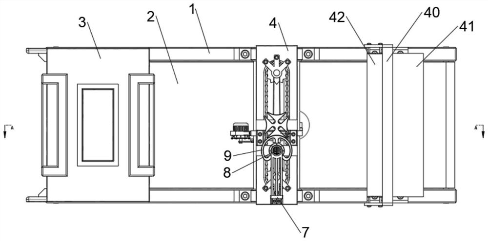
[0043] Please refer to figure 1 , figure 2 , image 3 , Figure 4 , Figure 5 and Figure 9 As shown, the intermittent assembly includes a fixed plate 6, a first motor 8, a rotating ring 9, a push rod 10, a first rotating shaft 11 and a sheave 12, the fixed plate 6 is fixedly installed on the top of the support frame 4, and the first motor 8 is fixed Installed on the inner side of the first fixing bracket 7, the first motor 8 is electrically connected to the equipment using the power supply, the output end of the bottom of the first motor 8 is fixedly connected with a rotating ring 9 for stopping rotation, and the rotating ring 9 is fixedly connected with a rotating ring 9 for pushing. The rotating push rod 10, the first rotating shaft 11 is rotatably connected to the fixed plate 6, the sheave 12 is fixedly connected to the top of the first rotating shaft 11, and the outer wall of the sheave 12 and the outer wall of the rotating ring 9 abut each other.

[0044] The trans...

Embodiment 3

[0048] Please refer to Figure 4 , Figure 7 and Figure 8 As shown, the drive assembly includes a second motor 22, a first rotating rod 23, a toothed rod 24, a third rotating shaft 25, a second gear 26 and a fitting block 27, and the outer wall of the movable plate 20 is fixedly connected with a second drive for driving. The motor 22 and the second motor 22 are electrically connected with the equipment using a power supply, one end of the first rotating rod 23 is fixedly connected to the output end of the second motor 22, and the other end of the first rotating rod 23 is fixedly connected with a toothed rod for reciprocating transmission 24. The third rotating shaft 25 is rotatably connected to the middle of the movable plate 20, the second gear 26 is fixedly connected to the outer side of the third rotating shaft 25, the top of the second gear 26 meshes with the bottom of the gear rod 24, and the fitting block 27 It is rotatably connected to the outer wall of the third rot...


PUM


Abstract

The invention discloses touch screen production equipment and a processing method thereof.The touch screen production equipment comprises a working frame, a transmission device used for transmitting screen glass is arranged on the inner side of the working frame, a cutting device used for cutting the screen glass is fixedly installed on the working frame, and a supporting frame is fixedly connected to the working frame through bolts; a transmission groove used for intermittent transmission is formed in the supporting frame, a transmission assembly used for intermittent transmission is arranged in the transmission groove, a material taking suction cup is pushed by a first fixed push plate to rotate in a rotating groove, then a piston block is made to block a vacuum hole, and after the material taking suction cup makes contact with screen glass, extrusion is conducted; and a closed space is formed in the material taking suction cup, then vacuum adsorption material taking of the screen glass is achieved, manual material taking operation steps are reduced, the problem that an equipment material taking tool inclines in the manual material taking process is solved, and then the material taking efficiency of the screen glass is improved.

Description

technical field [0001] The invention relates to the technical field of touch screen production, in particular to a touch screen production equipment and a processing method thereof. Background technique [0002] The mobile phone screen is also called the display screen, which is used to display images and colors. The screen size is calculated according to the diagonal of the screen, usually in inches, which refers to the length of the diagonal of the screen. The screen material is gradually popular with the color screen of mobile phones. The material of the mobile phone screen is also becoming more and more important. In the production process of the mobile phone screen, the display light group of the realistic color needs to be attached to a piece of glass. The mobile phone screen glass is produced by laser cutting a larger piece of glass. However, after the glass is cut, it needs to be collected and placed. At present, it is not possible to effectively take and place the g...

Claims


Application Information

Patent Timeline
IPC IPC(8): B65G49/06
CPCB65G49/061Y02P40/57
Inventor 肖斌张凯刘国华黄饶梁庆祝吕志勇
Owner ZHE JIANG CHANGXING HELI OPTOELECTRONIC TECH CO LTD
Why Eureka
Try Eureka