
Connector, lattice unit cell and assembled lattice structure

A connecting head and lattice technology, which is applied in the direction of connecting members, rod connections, building elements, etc., can solve problems such as low connection efficiency, and achieve the effects of improving production efficiency, reducing connection difficulty, and increasing connection strength.

Active Publication Date: 2022-07-29
BEIHANG UNIV
View PDF13 Cites 0 Cited by
  • Summary
  • Abstract
  • Description
  • Claims
  • Application Information

AI Technical Summary

Problems solved by technology

For this reason, the first purpose of the present invention is to propose a connector, through which the rapid assembly of the lattice structure can be realized and the strength of the connection point can be ensured, which solves the problem of multiple lattice cells passing through bolts in the prior art. The problem of low connection efficiency

Method used


Image

  • Connector, lattice unit cell and assembled lattice structure
  • Connector, lattice unit cell and assembled lattice structure
  • Connector, lattice unit cell and assembled lattice structure

Examples


Embodiment 1

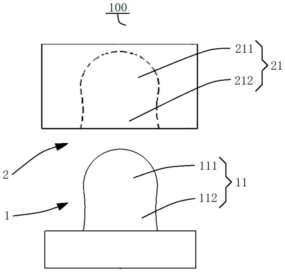
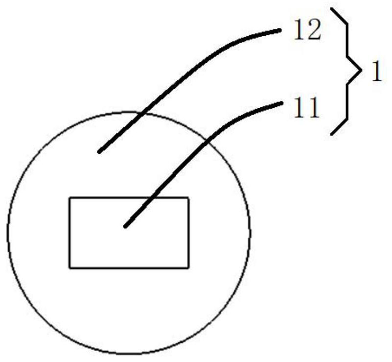
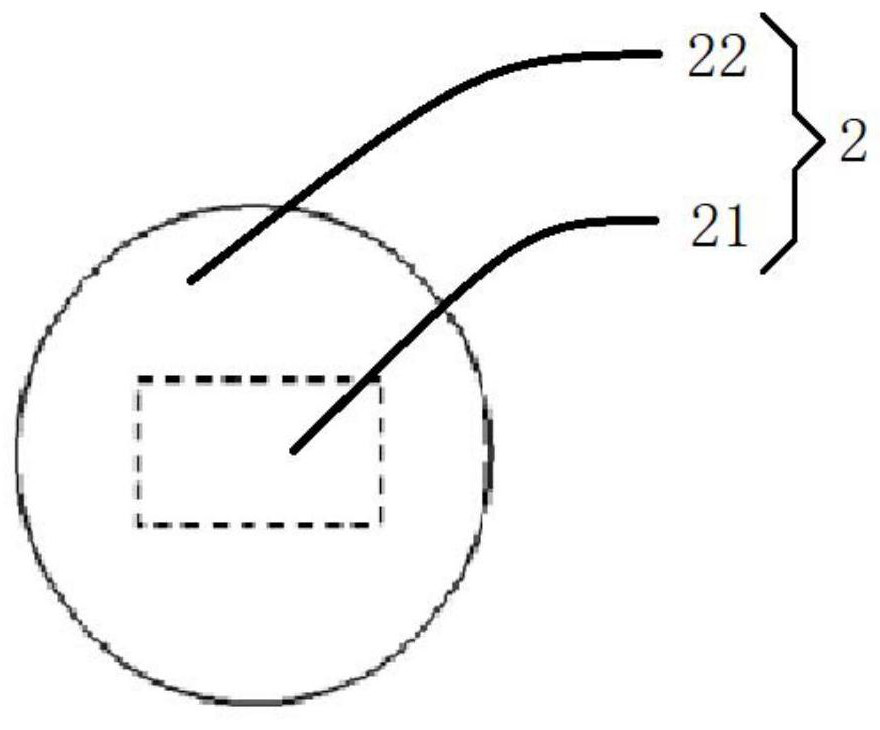
[0105] A connector 100, such as figure 1 As shown, it includes: a first connecting part 1 and a second connecting part 2 .

[0106] Wherein, one of the first connecting part 1 and the second connecting part 2 is provided with a protruding part 11, while the other is provided with a connecting groove 21, and the protruding part 11 can be connected with the connecting groove 21 to make the first connecting part 1 and the second connecting part 2 are connected.

[0107] like figure 1 As shown, the protruding portion 11 includes a pressing portion 111 and a necking portion 112 , and one end of the pressing portion 111 is connected to the necking portion 112 .

[0108] like figure 1 As shown, the connecting groove 21 includes a first connecting groove 211 and a second connecting groove 212 that communicate with each other. When the direction of the connecting groove 211 moves, the pressing portion 111 presses the groove wall of the second connecting groove 212 ;

Embodiment 2

[0110] A connector 100 is different from Embodiment 1 in that, on the basis of Embodiment 1, the extruded portion 111 and the necked portion 112 are flat structures, and at least part of the extruded portion 111 has a larger cross-sectional width than the necked portion. 112 The width of the cross section.

[0111] like image 3 As shown, the first end surface 1111 of the extruding portion 111 and the two second end surfaces 1121 of the necking portion 112 are both arc surfaces, and both sides of the first end surface 1111 are respectively connected with a second end surface 1121. Different from the curvature of the second end surface 1121 .

[0112] like image 3 As shown, the two second end surfaces 1121 are arranged symmetrically with the central axis of the first end surface 1111 as the axis, and the first end surface 1111 and the second end surface 1121 intersect at the same horizontal plane to form a first circular arc line and two second circular arc lines , the line...

Embodiment 3

[0114] A connector 100 is different from Embodiment 1 in that, on the basis of Embodiment 1, such as Image 6 As shown, at least one elastic protrusion 213 is formed in the connecting groove 21 to protrude inwardly, and the corresponding elastic protrusion 213 is provided with a corresponding avoidance hole 113 on the protrusion 11. When the protrusion 11 is connected to the connecting groove 21, The elastic protrusions 213 are matched with the avoidance holes 113 .


PUM


Abstract

The invention discloses a connector, a lattice unit cell and an assembled lattice structure, and the connector comprises a first connecting part and a second connecting part. One of the two connecting parts is provided with a protruding part, the other connecting part is provided with a connecting groove, and the protruding part is connected with the connecting groove to enable the first connecting part to be connected with the second connecting part; the protruding part comprises an extrusion part and a necking part, and the extrusion part is connected with the necking part; the connecting groove comprises a first connecting groove body and a second connecting groove body which communicate with each other, the second connecting groove body is open towards the side away from the first connecting groove body, and when the extrusion part moves from the opening to the first connecting groove body, the extrusion part extrudes the groove wall of the second connecting groove body; and when the extrusion part is connected with the first connecting groove, the necking part is connected with the second connecting groove. According to the connector, the protruding part is arranged on one connecting part, the connecting groove matched with the protruding part is formed in the other connecting part, the protruding part and the connecting groove are matched so that the connecting strength of the first connecting part and the second connecting part can be improved, and the structure is stable after the connector is connected.

Description

technical field [0001] The invention belongs to the technical field of material processing, in particular to a connector, a lattice unit cell and an assembled lattice structure. Background technique [0002] As an ordered porous structure, the lattice structure has better mechanical properties than traditional disordered porous structures such as foam. It is currently recognized as the most effective engineering weight reduction scheme to meet the structural weight reduction of large aerospace components. , reduce energy consumption, improve the bearing efficiency of the structure and have the advantages of energy absorption and heat transfer. [0003] However, limited by the complex geometry and processing technology of the lattice structure, it is difficult to achieve mass production of complete lattice structures. Although 3D printing technology can realize the overall manufacture of lattice structural parts, the preparation cost is high and the processing efficiency is ...

Claims


Application Information

Patent Timeline
Patent Type & Authority Applications(China)
IPC IPC(8): F16B7/04F16B2/22F16S3/08
CPCF16B7/044F16B2/22F16S3/08Y02E60/10
Inventor 殷莎黄瑶杨瑞恒郭维华
Owner BEIHANG UNIV
Learn More