Air pre-heater capable of automatically cleaning deposits and method

An air preheater and self-cleaning technology, applied in combustion methods, indirect heat exchangers, cleaning heat transfer devices, etc., can solve problems such as easy blockage of air preheaters, and achieve the effect of improving heat exchange efficiency

Pending Publication Date: 2022-07-29
SHANGHAI YIFENG ELECTRICAL & MECHANICAL TECH DEV
View PDF0 Cites 0 Cited by
  • Summary
  • Abstract
  • Description
  • Claims
  • Application Information

AI Technical Summary

Problems solved by technology

[0005] An object of the present invention is to propose a self-cleaning and deposited air preheater to solve the problem that the existing air preheater is easy to block

Method used


Image

  • Air pre-heater capable of automatically cleaning deposits and method
  • Air pre-heater capable of automatically cleaning deposits and method
  • Air pre-heater capable of automatically cleaning deposits and method

Examples


Embodiment Construction

[0029] The following describes in detail the embodiments of the present invention, examples of which are illustrated in the accompanying drawings, wherein the same or similar reference numerals refer to the same or similar elements or elements having the same or similar functions throughout. The embodiments described below with reference to the accompanying drawings are exemplary, and are intended to explain the present invention and should not be construed as limiting the present invention.

[0030] In the description of the present invention, it should be understood that the terms "upper", "lower", "front", "rear", "left", "right", "vertical", "horizontal", "top", The orientation or positional relationship indicated by "bottom", "inner", "outer", etc. is based on the orientation or positional relationship shown in the accompanying drawings, and is only for the convenience of describing the present invention and simplifying the description, rather than indicating or implying t...


PUM


Abstract

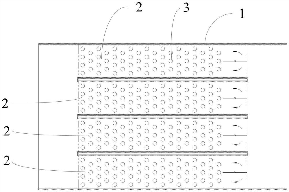
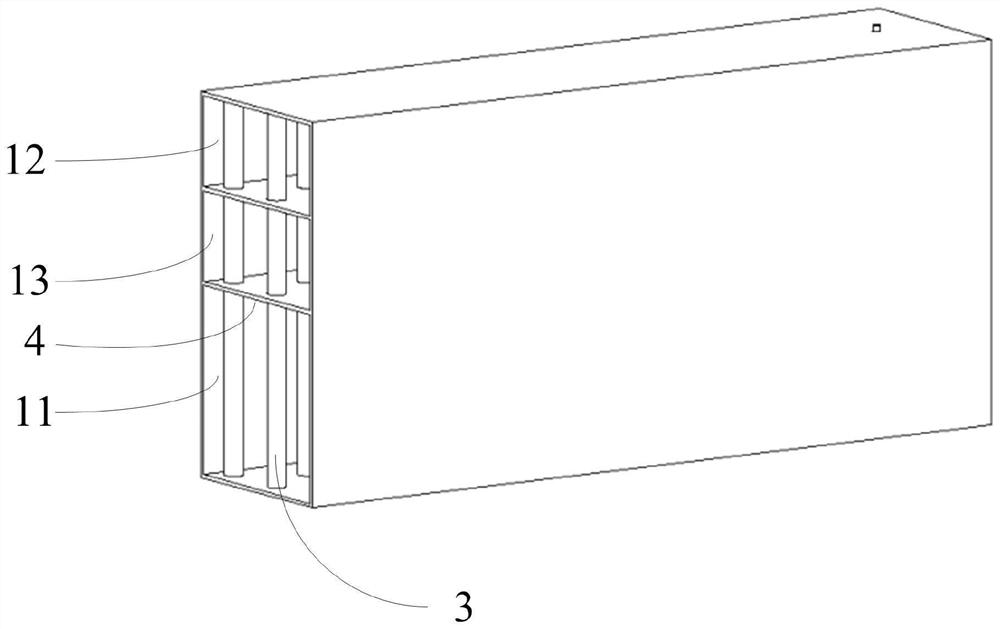
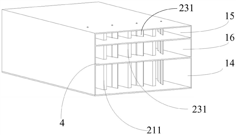
The air pre-heater comprises a shell and a plurality of horizontally-arranged heat exchange units arranged in a cavity of the shell, and each heat exchange unit sequentially comprises a flue pipe, a second air pipe, a first air pipe and heat pipes from bottom to top, the flue pipe, the second air pipe and the first air pipe are separated from one another and do not communicate with one another, and the heat pipes vertically penetrate through the flue pipe, the second air pipe and the first air pipe in sequence; the flowing direction of hot flue gas in the flue pipe is opposite to the flowing direction of cold air in the air pipe; the two ends of all the flue pipes share a flue gas main inlet and a flue gas main outlet, and the two ends of all the second air pipes share a secondary air main outlet and a secondary air main inlet; two ends of all the air pipes I share a primary air main outlet and a primary air main inlet; a flue gas guide door is arranged on the flue gas outlet side of each flue pipe; the cold air inlet of each air pipe is provided with a cold air guide door. By adjusting the input heat of the flue gas channel of one heat exchange unit to be increased and the output heat to be reduced, the temperature of the flue gas pipe of the heat exchange unit is increased, and deposits attached to the heat pipe in the heat exchange unit are removed; and the rest heat exchange units are removed in sequence, and deposition of the air pre-heater is removed integrally.

Description

technical field [0001] The invention relates to the technical field of gas heat exchange, in particular to a self-cleaning deposition air preheater and a method. Background technique [0002] The air preheater is a kind of preheating equipment that improves the heat exchange performance of the boiler and reduces the heat loss. The function of the air preheater is to conduct the heat carried in the flue gas discharged from the flue at the tail of the boiler to the air before entering the boiler through the heat sink, and preheat the air to a certain temperature. At present, most of the air preheaters of coal-fired power station boilers are rotary air preheaters. Take the three-silo rotary air preheater as an example. The three-silo rotary air preheater is a regenerative air preheater. When the rotor rotates, the flue gas Alternately flow through the heat storage element with the air. When the flue gas flows, the heating surface absorbs heat, and then transfers to the heating...

Claims


Application Information

Patent Timeline
Patent Type & Authority Applications(China)
IPC IPC(8): F23L15/00F23J15/06F28D15/02F28G13/00
CPCF23L15/00F23J15/06F28D15/02F28G13/005
Inventor 陈刚杨博
Owner SHANGHAI YIFENG ELECTRICAL & MECHANICAL TECH DEV
Why Eureka
Try Eureka