Laser welding method of aircraft metal pressure measuring capillary
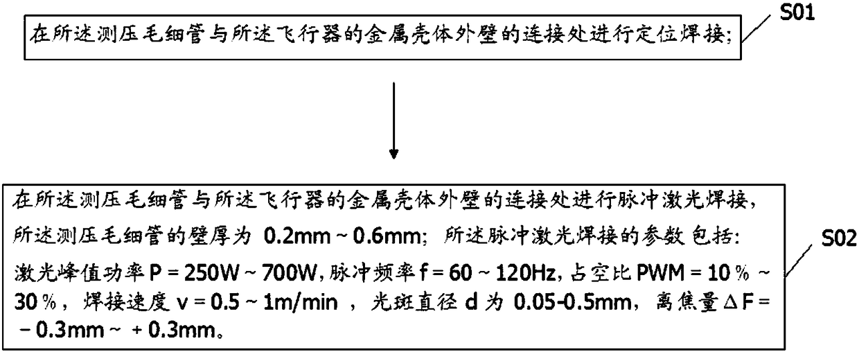
A laser welding and capillary technology, which is applied in laser welding equipment, welding equipment, metal processing equipment, etc., can solve the problem of inability to achieve laser welding between the metal pressure measuring capillary and the outer wall of the metal shell of the aircraft, poor welding quality, and low joint strength. Problems, to improve programming efficiency and achieve the effect of large weld depth-to-width ratio and high-temperature strength
- Summary
- Abstract
- Description
- Claims
- Application Information
AI Technical Summary
Problems solved by technology
Method used
Image
Examples
Embodiment 1
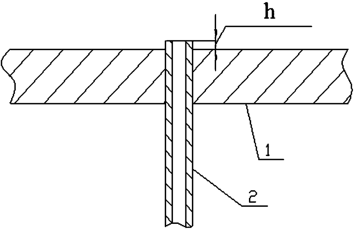
[0066] Embodiment 1 of the present invention is the laser welding method of the metal pressure-measuring capillary of the aircraft. When the parts are processed, the outer wall of the metal shell of the aircraft is designed to measure the aerodynamic pressure. Diameter; the processed metal pressure measuring capillary is inserted into the through hole of the outer wall of the metal shell of the aircraft, and the end surface of the pressure measuring capillary is higher than the surface of the outer wall of the aircraft h=0.1 ~ 0.2mm, such as image 3 shown.
[0067] The welding method of the metal pressure measuring capillary comprises the steps:
[0068] S101: Positioning welding is required before the pressure measuring capillary is welded to the side wall of the metal shell to ensure that the assembly state of the two does not change, and laser dot positioning welding is performed around the pressure measuring tube, such as Figure 4 As shown, the four places 5-1 to 5-4 ar...
Embodiment 2
[0073] Embodiment 2 of the present invention is the laser welding method of the metal pressure-measuring capillary of the aircraft. When the parts are processed, the outer wall of the metal shell of the aircraft is designed to measure the aerodynamic pressure. diameter; the processed metal pressure measuring capillary is inserted into the through hole of the outer wall of the metal shell of the aircraft, and the end surface of the pressure measuring capillary is 0.1-0.2 mm higher than the surface of the outer wall of the aircraft, such as image 3 shown.
[0074] The welding method of the metal pressure measuring capillary comprises the steps:
[0075] S201: Positioning welding is required before the pressure measuring capillary is welded to the side wall of the metal shell to ensure that the assembly state of the two does not change, and laser dot positioning welding is performed around the pressure measuring tube, such as Figure 4 As shown, the four locations of 5-1 to 5-4...
Embodiment 3
[0084] Embodiment 3 of the present invention is the laser welding method of the metal pressure-measuring capillary of the aircraft. When the parts are processed, the outer wall of the metal shell of the aircraft is designed to measure the aerodynamic pressure. diameter; the processed metal pressure measuring capillary is inserted into the through hole of the outer wall of the metal shell of the aircraft, and the end surface of the pressure measuring capillary is 0.1-0.2 mm higher than the surface of the outer wall of the aircraft, such as image 3 shown.
[0085] The welding method of the metal pressure measuring capillary comprises the steps:
[0086] S301: Positioning welding is required before the pressure measuring capillary is welded to the side wall of the metal shell to ensure that the assembly state of the two does not change, and laser dot positioning welding is performed around the pressure measuring tube, such as Figure 4 As shown, the four positions of 5-1 to 5-4...
PUM
| Property | Measurement | Unit |
|---|---|---|
| thickness | aaaaa | aaaaa |
| thickness | aaaaa | aaaaa |
| thickness | aaaaa | aaaaa |
Abstract
Description
Claims
Application Information
 - R&D
- Intellectual Property
- Life Sciences
- Materials
- Tech Scout
- Unparalleled Data Quality
- Higher Quality Content
- 60% Fewer Hallucinations
Browse by: Latest US Patents, China's latest patents, Technical Efficacy Thesaurus, Application Domain, Technology Topic, Popular Technical Reports.
© 2025 PatSnap. All rights reserved.Legal|Privacy policy|Modern Slavery Act Transparency Statement|Sitemap|About US| Contact US: help@patsnap.com


