Device and method for high-precision adjustment and separation of parallelism of laser beams

A laser beam, parallelism technology, applied in measuring devices, instruments, steering induction equipment, etc., can solve the problems of difficult laser parallelism adjustment and low adjustment accuracy.

Active Publication Date: 2022-07-29
INNOVATION ACAD FOR PRECISION MEASUREMENT SCI & TECH CAS
View PDF7 Cites 0 Cited by
  • Summary
  • Abstract
  • Description
  • Claims
  • Application Information

AI Technical Summary

Problems solved by technology

[0004] To adjust the parallelism of the separated laser beams and the coincidence of the incident light and the reflected light, the general method is to use the diaphragm to complete, a pair of reference diaphragms are placed in parallel with the other pair of diaphragms, and the centers of the two pairs of diaphragms are kept parallel. The two beams of light pass through the centers of the two pairs of apertures at the same time, and a pair of parallel beams can be obtained. The position of the spot is adjusted by using a polarization beam splitter, a reticle, etc., and the overlap of the beams is realized. However, the adjustment accuracy of this method is relatively low. Low; Another method is to use an autocollimator to assist in the calibration of beam parallelism and coincidence. It is difficult to adjust the laser parallelism with a large separation distance, and

Method used


Image

  • Device and method for high-precision adjustment and separation of parallelism of laser beams
  • Device and method for high-precision adjustment and separation of parallelism of laser beams
  • Device and method for high-precision adjustment and separation of parallelism of laser beams

Examples


Embodiment 1

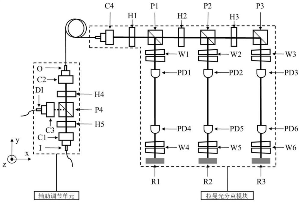
[0031] like figure 1 As shown in the figure, a device for adjusting the parallelism of separated laser beams with high precision includes a Raman beam splitting module, an auxiliary adjustment unit, a laser, a position-sensitive quadrant photodiode, a three-coordinate measuring instrument, and a precision displacement stage.

[0032] The optical path in the auxiliary adjustment unit and the optical path in the Raman beam splitting module are all in the xy plane, where the direction of the light source beam of the laser is parallel to the x-axis, and the directions of the three Raman beams in the Raman beam splitting module are the same as The y-axis is parallel, and the upper surface of the quartz substrate is parallel to the xy plane, intersecting with the negative semi-axis of the z-axis.

[0033] The auxiliary adjustment unit includes a first fiber coupler C1, a fifth half-wave plate H5, a fourth polarization beam splitter prism P4, a third fiber coupler C3, a fourth half-w...


PUM

PropertyMeasurementUnit
refractive indexaaaaaaaaaa

Abstract

The invention discloses a device for high-precision adjustment and separation of parallelism of laser beams. The device comprises a Raman light beam splitting module, an auxiliary adjustment unit, a laser light source, a position sensitive quadrant photodiode, a three-coordinate measuring instrument, a precision displacement table and the like. The invention further discloses a method for adjusting the parallelism of the separated laser beams at high precision, high-precision parallelism of three beams of Raman light and high coincidence of reverse light beams in the atomic interference gyroscope are realized by utilizing mutual cooperation of a three-coordinate instrument and a position sensitive quadrant photodiode, the method does not depend on the atomic interference process, and the total error is smaller than 57.6 microrad. In addition, the optical element and the quartz substrate are bonded and fixed by utilizing a hydroxyl catalytic bonding technology, so that a new way is provided for stably keeping high-precision parallelism of three beams of Raman light, and engineering application of the atom interference gyroscope is promoted.

Description

technical field [0001] The invention relates to the technical field of optical precision calibration, in particular to a device for adjusting the parallelism of a split laser beam with high precision, and a method for adjusting the parallelism of a split laser beam with high precision. technical background [0002] As a new type of inertial measurement instrument, the atomic interferometric gyroscope has the potential of high measurement accuracy, and provides a new technical means for the precise measurement of rotation, and is gradually applied in the fields of basic science and engineering technology. In order to improve the index of the atomic interference gyroscope, it is a more effective way to increase the area of ​​the interference loop. However, the construction of a large-area interference loop requires precise control of the wave vector direction of the Raman light to meet the closing requirements of the interference loop, so the parallelism between the separated ...

Claims


Application Information

Patent Timeline
Patent Type & Authority Applications(China)
IPC IPC(8): G01C19/58G01C25/00
CPCG01C19/58G01C25/005
Inventor 孙川鲁思滨姚战伟李润兵蒋敏李少康陈小莉王谨詹明生
Owner INNOVATION ACAD FOR PRECISION MEASUREMENT SCI & TECH CAS
Why Eureka
Try Eureka