Supercharge Your Innovation With Domain-Expert AI Agents!

PCB test fixture positioning pin and manufacturing method thereof

A technology for testing fixtures and PCB boards, which is applied in the direction of electronic circuit testing and measuring device casings, etc. It can solve the problems of low strength, short service life, and easy damage of positioning pins, and achieves increased anti-wear effects, simple manufacturing, and unbreakable effect

Pending Publication Date: 2022-07-29
苏州中熙精密电机有限公司
View PDF0 Cites 0 Cited by
  • Summary
  • Abstract
  • Description
  • Claims
  • Application Information

AI Technical Summary

Problems solved by technology

[0003] There are certain disadvantages in the use of the existing positioning pins of PCB board test fixtures. First, the use strength of the positioning pins may be low during use, which is prone to damage and has a short service life, which is not conducive to people's use. , in addition, it is relatively complicated to prepare, which brings certain adverse effects to people's use process. Therefore, we propose a PCB board test fixture positioning pin and its manufacturing method

Method used


Image

  • PCB test fixture positioning pin and manufacturing method thereof
  • PCB test fixture positioning pin and manufacturing method thereof
  • PCB test fixture positioning pin and manufacturing method thereof

Examples


Embodiment 1

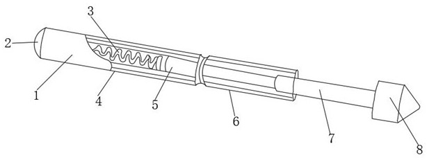
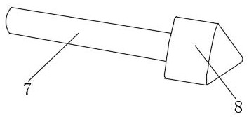
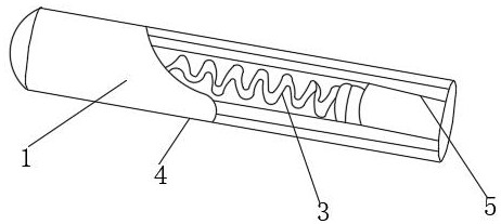
[0031] like Figure 1-4 As shown, a PCB board test fixture positioning needle includes a needle body 1, a needle holder 6 and a needle head 8. A needle tail 2 is arranged at the tail of the needle body 1, and a spring 3 is arranged inside the needle body 1. A piston 5 is installed at the end, a needle rod 7 is installed between the needle holder 6 and the needle head 8 , and a reinforcing shell 4 is installed on the outer wall of the needle body 1 .

[0032] Further, the reinforcing shell 4 includes a galvanized layer 9, a metal fiber layer 10, a polymer material layer 11, a copper alloy layer 12 and an aluminum alloy layer 13. The galvanized layer 9 is located on the outer surface of the metal fiber layer 10, and the metal fiber layer 10 It is located on the outer surface of the polymer material layer 11 , the polymer material layer 11 is located on the outer surface of the copper alloy layer 12 , and the copper alloy layer 12 is located on the outer surface of the aluminum a...

Embodiment 2

[0044] On the basis of Example 1, as Figure 1-4 As shown, a PCB board test fixture positioning needle includes a needle body 1, a needle holder 6 and a needle head 8. A needle tail 2 is arranged at the tail of the needle body 1, and a spring 3 is arranged inside the needle body 1. A piston 5 is installed at the end, a needle rod 7 is installed between the needle holder 6 and the needle head 8 , and a reinforcing shell 4 is installed on the outer wall of the needle body 1 .

[0045] Further, the reinforcing shell 4 includes a galvanized layer 9, a metal fiber layer 10, a polymer material layer 11, a copper alloy layer 12 and an aluminum alloy layer 13. The galvanized layer 9 is located on the outer surface of the metal fiber layer 10, and the metal fiber layer 10 It is located on the outer surface of the polymer material layer 11 , the polymer material layer 11 is located on the outer surface of the copper alloy layer 12 , and the copper alloy layer 12 is located on the outer ...


PUM


Abstract

The invention discloses a PCB test fixture positioning pin and a manufacturing method thereof, the PCB test fixture positioning pin comprises a pin body, a pin holder and a pin head, the tail of the pin body is provided with a pin tail, the pin body is internally provided with a spring, the end part of the spring is provided with a piston, a pin rod is installed between the pin holder and the pin head, the outer wall of the pin body is provided with a reinforcing shell, and the reinforcing shell is provided with a through hole. The reinforced shell comprises a zinc coating, a metal fiber layer, a high polymer material layer, a copper alloy layer and an aluminum alloy layer, the zinc coating is located on the outer surface of the metal fiber layer, and the metal fiber layer is located on the outer surface of the high polymer material layer. According to the PCB test jig positioning pin and the manufacturing method thereof, the reinforced shell and the galvanized material layer are arranged, so that the use strength of the positioning pin can be improved, damage is not prone to occurring, the service life of the positioning pin is prolonged, the anti-abrasion effect of the outer surface of the positioning pin can be improved, the use strength is further improved, and manufacturing is simpler.

Description

technical field [0001] The invention relates to the field of PCB board testing, in particular to a PCB board testing fixture positioning pin and a manufacturing method thereof. Background technique [0002] PCB board test fixture positioning pin is a kind of support device for positioning the PCB board during testing. When testing the PCB board, it is necessary to locate the four corners of the board first to prevent the deviation during testing. In fact, with the continuous development of technology, people have higher and higher requirements for the manufacturing process of PCB board test fixture positioning pins. [0003] The existing PCB board test fixture positioning pins have certain disadvantages in use. First of all, the use strength of the positioning pins may be low during use, which is prone to damage and has a short service life, which is not conducive to people's use. , and also, the preparation is more complicated, which brings certain adverse effects to peopl...

Claims


Application Information

Patent Timeline
Patent Type & Authority Applications(China)
IPC IPC(8): G01R31/28G01R1/04
CPCG01R31/2808G01R1/0408
Inventor 龙慧梅贺小华
Owner 苏州中熙精密电机有限公司
Features
  • R&D
  • Intellectual Property
  • Life Sciences
  • Materials
  • Tech Scout
  • Unparalleled Data Quality
  • Higher Quality Content
  • 60% Fewer Hallucinations
Learn More