Optical lens
An optical lens and optical total length technology, applied in the field of optical lenses, can solve the problems of difficult to increase the screen ratio, large head size, difficult to capture pictures, etc., and achieve the effect of good image quality and total length.
- Summary
- Abstract
- Description
- Claims
- Application Information
AI Technical Summary
Problems solved by technology
Method used
Image

Examples
no. 1 example
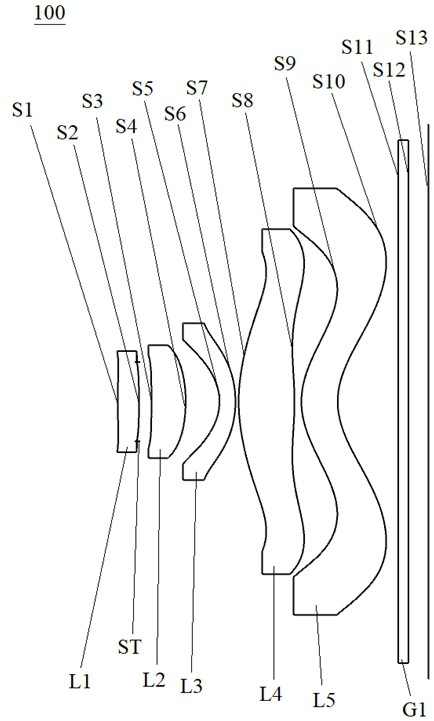
[0077] see figure 1 , which is a schematic structural diagram of the optical lens 100 provided in the first embodiment of the present invention. The optical lens 100 sequentially includes a first lens L1, a diaphragm ST, and a second lens L2 along the optical axis from the object side to the imaging surface S13. , the third lens L3, the fourth lens L4, the fifth lens L5 and the filter G1.
[0078] Wherein, the first lens L1 has a positive refractive power, and both the object side S1 and the image side S2 of the first lens are convex;
[0079] The second lens L2 has positive refractive power, the object side S3 of the second lens is concave, and the image side S4 of the second lens is convex;
[0080] The third lens L3 has negative refractive power, the object side S5 of the third lens is concave, and the image side S6 of the third lens is convex;
[0081] The fourth lens L4 has positive refractive power, the object side S7 of the fourth lens is convex at the near optical ax...
no. 2 example
[0093] see Figure 4 , which is a schematic structural diagram of the optical lens 200 provided in the second embodiment of the present invention. The optical lens 200 of this embodiment is substantially the same as the above-mentioned first embodiment, and the main difference is that the image side S2 of the first lens L1 It is concave at the near optical axis, the object side S3 of the second lens L2 is convex at the near optical axis, and the curvature radius, aspheric coefficient, thickness and material of each lens are different.
[0094] Specifically, the design parameters of the optical lens 200 provided in this embodiment are shown in Table 3.
[0095] table 3
[0096]
[0097] Table 4 shows the surface shape coefficients of each aspherical surface of the optical lens 200 in this embodiment.
[0098] Table 4
[0099]
[0100] Please refer to Figure 5 , Image 6 , which are the field curvature graph and the vertical axis chromatic aberration graph of the opt...
no. 3 example
[0102] like Figure 7 As shown, it is a schematic structural diagram of the optical lens 300 provided in this embodiment. The optical lens 300 of this embodiment is substantially the same as the above-mentioned first embodiment, except that the object side S1 of the first lens L1 is concave, and the second lens L1 is concave. The object side surface S3 of the lens L2 is a convex surface at the near optical axis, and the curvature radius, aspheric coefficient, thickness and material of each lens surface are different.
[0103] Specifically, the design parameters of the optical lens 300 provided in this embodiment are shown in Table 5.
[0104] table 5
[0105]
[0106] Table 6 shows the surface shape coefficients of each aspherical surface of the optical lens 300 in this embodiment.
[0107] Table 6
[0108]
[0109] Please refer to Figure 8 , Figure 9 , which are the field curvature graph and the vertical axis chromatic aberration graph of the optical lens 300, re...
PUM
 Abstract
Description
Claims
Application Information
 - R&D Engineer
- R&D Manager
- IP Professional
- Industry Leading Data Capabilities
- Powerful AI technology
- Patent DNA Extraction
Browse by: Latest US Patents, China's latest patents, Technical Efficacy Thesaurus, Application Domain, Technology Topic.
© 2024 PatSnap. All rights reserved.Legal|Privacy policy|Modern Slavery Act Transparency Statement|Sitemap