Cutter path control method applied to numerical control system

A tool path and control method technology, applied in the direction of digital control, electrical program control, etc., can solve the problems of reduced machining accuracy, low sampling rate, and unsmooth movement of the servo controller, so as to reduce busyness and improve performance and stability Effect

Pending Publication Date: 2022-07-29
英诺威讯智能科技(杭州)有限公司
View PDF0 Cites 0 Cited by
  • Summary
  • Abstract
  • Description
  • Claims
  • Application Information

AI Technical Summary

Problems solved by technology

[0002] In the process of CNC machining, the servo interface of the current servo controller uses a high sampling rate (that is, the sampling period is short) for the data instructions sent by the CNC controller. The internal servo interface of the CNC controller is compared with the servo interface of the servo controller The use of low sampling rate (that is, the sampling period is longer), which leads to the servo controller not being smooth when controlling the movement of the servo motor, causing the servo motor to move discontinuously during the motion process, and sometimes it is necessary to use multiple servo motors to control The tool moves, which will cause all the vibration of the servo motor to be transmitted to the tool at the end, so that the motion curve of the drive is a stepped curve image instead of a smooth curve image, such as figure 1 As shown, this will reduce the machining accuracy of the tool due to vibration during machining

Method used


Image

  • Cutter path control method applied to numerical control system
  • Cutter path control method applied to numerical control system
  • Cutter path control method applied to numerical control system

Examples


Embodiment Construction

[0028] The present invention will be further described and described in detail below with reference to the specific embodiments and the accompanying drawings. Those of ordinary skill in the art will be able to implement the present invention based on these descriptions. In addition, the embodiments of the present invention referred to in the following description are generally only some embodiments of the present invention, not all of the embodiments. Therefore, based on the embodiments of the present invention, all other embodiments obtained by persons of ordinary skill in the art without creative work shall fall within the protection scope of the present invention. Unless otherwise specified, the methods briefly described in the embodiments of the present invention are all methods mastered by those skilled in the art.

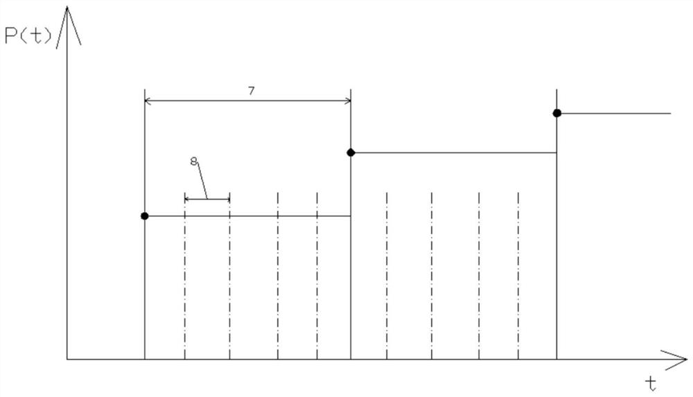
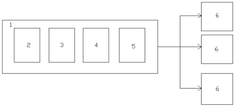
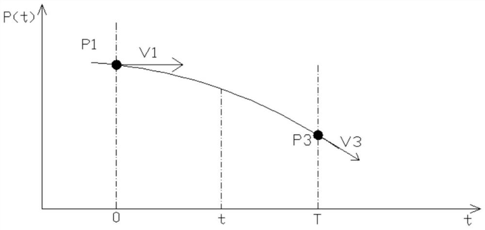
[0029] Attached below Figure 2-4 Further explanation for this application:

[0030] As one of the embodiments of the present invention, a tool path contr...


PUM


Abstract

The invention relates to a cutter path control method applied to a numerical control system, the numerical control system comprises a CNC main controller and a plurality of servo controllers, each servo controller is connected with the CNC main controller, and the CNC main controller comprises a human-computer interface main controller, a compiler, an interpolation compiler and an interpolation actuator; the human-computer interface controller is used for outputting processing information and displaying an image transmitted by the compiler; and the compiler is used for receiving the processing information transmitted by the human-computer interface controller, processing the processing information into corresponding images and transmitting the images back to the human-computer interface controller, so that the driving part can stably and continuously move through the control method instead of rapidly starting and rapidly pausing discontinuous movement. Therefore, the situation that the machining precision is affected by intermittent shaking caused by multiple times of quick start and quick pause of the driving part in the moving process of the tool can be avoided.

Description

technical field [0001] The invention belongs to the technical field of numerical control machining, in particular to a tool path control method applied to a numerical control system. Background technique [0002] In the process of CNC machining, the current servo interface of the servo controller uses a high sampling rate (that is, the sampling period is short) for the data commands sent by the CNC controller, and the internal servo interface of the CNC controller is relative to the servo interface of the servo controller. Using a low sampling rate (that is, the sampling period is long), the servo controller is not smooth when controlling the movement of the servo motor, resulting in the discontinuous movement of the servo motor during the movement, and sometimes it is necessary to use multiple servo motors to control The tool moves, which will cause the jitter of all servo motors to be transmitted to the tool at the end, so that the motion curve of the driving part is a ste...

Claims


Application Information

Patent Timeline
Patent Type & Authority Applications(China)
IPC IPC(8): G05B19/19
CPCG05B19/19G05B2219/35349
Inventor 黄加园陈田田弗兰克纳塔鹏邵望臻杨振宇茹开开
Owner 英诺威讯智能科技(杭州)有限公司
Why Eureka
Try Eureka