Pipeline internal cooling type evaporative cooling structure suitable for vertical motor rotor

A technology for evaporative cooling and vertical motors, which is applied in the direction of magnetic circuit shape/style/structure, winding conductor shape/style/structure, cooling/ventilation devices, etc. Problems such as limitations in the scope of use, achieve the effect of simple and reliable structure, good sealing, and improve technical difficulty and process difficulty.

Pending Publication Date: 2022-07-29
INST OF ELECTRICAL ENG CHINESE ACAD OF SCI
View PDF0 Cites 0 Cited by
  • Summary
  • Abstract
  • Description
  • Claims
  • Application Information

AI Technical Summary

Problems solved by technology

However, the water internal cooling method also has its inherent disadvantages: a water purification system needs to be installed, which increases the complexity of the system; the interior of the hollow copper wire is oxidized by oxygen ions in the water to form deposits that block the pipe; water leakage at the water joint or other seals causes short-circuit accidents, etc.
However, this structure must use hollow wires as the rotor pole coils, and the pole coils must be wound in a flat-winding manner, which has limitations in the scope of use; and once this long pipe structure is applied to a large motor rotor, it will expose the inner bending. Problems with many channels, long pipeline distances and large flow resistance

Method used


Image

  • Pipeline internal cooling type evaporative cooling structure suitable for vertical motor rotor
  • Pipeline internal cooling type evaporative cooling structure suitable for vertical motor rotor
  • Pipeline internal cooling type evaporative cooling structure suitable for vertical motor rotor

Examples


Embodiment Construction

[0042] In order to make the objectives, technical solutions and advantages of the present invention clearer, the present invention will be further described in detail below with reference to the accompanying drawings and embodiments. It should be understood that the specific embodiments described herein are only used to explain the present invention, but not to limit the present invention. In addition, the technical features involved in the various embodiments of the present invention described below can be combined with each other as long as they do not conflict with each other.

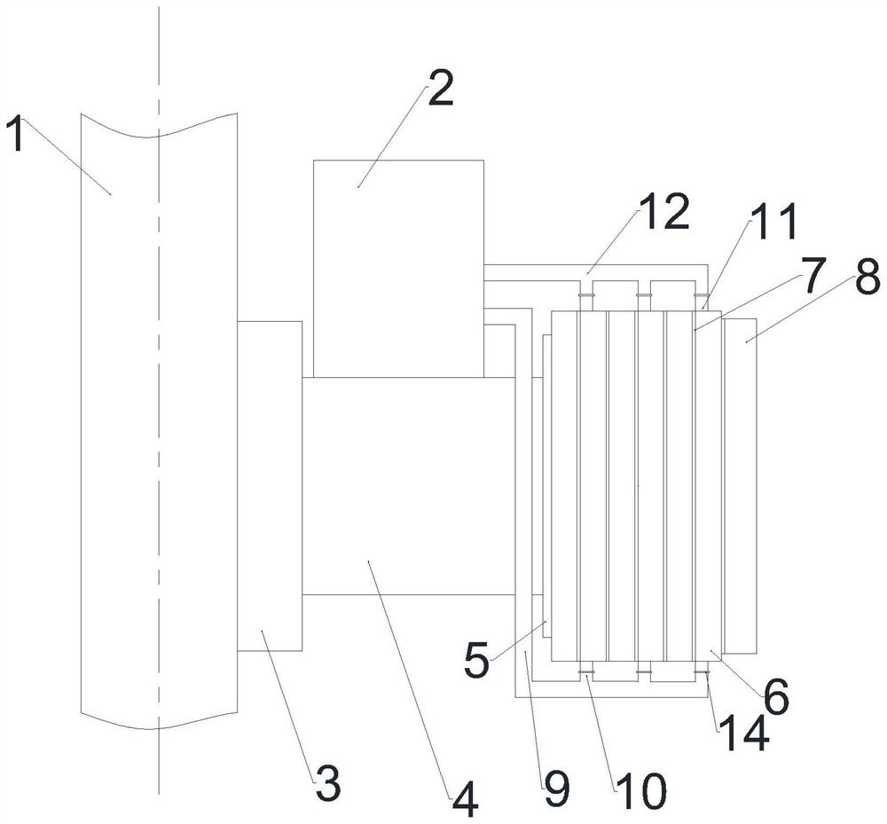
[0043] The present invention is applied to the rotor poles of vertical motors, such as Figure 1-6 As shown, the rotating shaft 1, the rotor support 3 and the magnetic yoke 4 together constitute the rotor support structure of the vertical motor, and the pole body 5, the magnetic pole coil 6 and the pole shoe 8 together constitute the magnetic pole structure of the vertical motor. The rotor support ...


PUM


Abstract

The invention discloses a pipeline internal cooling type evaporative cooling structure suitable for a vertical motor rotor. The pipeline internal cooling type evaporative cooling structure comprises a condenser, a pole coil, a cooling pipeline, a gas collecting pipe, a liquid return pipe and a liquid distribution pipe. The cooling pipeline is embedded into a pre-processed groove of the pole coil, the cooling pipeline is filled with a liquid evaporative cooling medium, and in a static state, the liquid level of the cooling medium in the cooling pipeline is higher than the highest position of the pole, namely, the length of the cooling pipeline embedded into the pole coil is full of the cooling medium. The cooling pipelines are connected at the upper ends of the magnetic poles through gas collecting pipes, and gaseous cooling media generated in the cooling pipelines flow to the condenser through the gas collecting pipes. A liquid cooling medium generated by condensation of the condenser flows into a cooling pipeline in the pole coil from the lower end through a liquid return pipe from an outlet of the condenser, and circulation is completed.

Description

technical field [0001] The invention relates to the field of vertical motor rotors, in particular to a pipeline internal cooling type evaporative cooling structure suitable for vertical motor rotors. Background technique [0002] The hydro-generator is developing towards large capacity and high speed. In order to meet the needs of improving power generation efficiency and reducing operating costs, it is necessary to further increase the single-unit capacity and the capacity of each pole. As the capacity of each pole of the generator increases, the problem of rotor heating becomes more and more serious, and the problem of temperature rise needs to be solved urgently. The rotor position of the hydro-generator is close to the axis of the generator, the space is limited, and it is in a rotating state, so it is difficult to add a large cooling device to effectively cool it. The traditional air-cooling method can only be applied to low-speed hydro-generators, and it is difficult ...

Claims


Application Information

Patent Timeline
Patent Type & Authority Applications(China)
IPC IPC(8): H02K9/20H02K1/32H02K9/19H02K9/197H02K3/04
CPCH02K9/20H02K1/32H02K9/19H02K9/197H02K3/04
Inventor 阮琳李瑞玮王宇
Owner INST OF ELECTRICAL ENG CHINESE ACAD OF SCI
Why Eureka
Try Eureka