Splicing tool and mounting method of permanent magnet alternating current servo motor magnetic steel

A technology of AC servo and installation method, applied in the direction of manufacturing stator/rotor body, etc., can solve the problems of inconvenient, cumbersome and time-consuming installation of magnetic steel, affecting installation, etc., to achieve fast and convenient installation, improve installation convenience, and guarantee The effect of consistency

Pending Publication Date: 2022-07-29
上海莘汭驱动技术有限公司
View PDF0 Cites 0 Cited by
  • Summary
  • Abstract
  • Description
  • Claims
  • Application Information

AI Technical Summary

Problems solved by technology

[0005] In view of the above-mentioned related technologies, the inventor believes that the installation method of the inner and outer sleeves requires a large suction force between the magnet and the mold to resist the interaction force between adjacent magnets. If the magnetic force is insufficient during installation, it will cause The movement of the magnetic steel affects the installation; it is cumbersome and time-consuming to dismantle and replace the true and false magnetic steel one by one with the help of ring tooling
Therefore, the current installation method of magnetic steel is relatively inconvenient.

Method used


Image

  • Splicing tool and mounting method of permanent magnet alternating current servo motor magnetic steel
  • Splicing tool and mounting method of permanent magnet alternating current servo motor magnetic steel
  • Splicing tool and mounting method of permanent magnet alternating current servo motor magnetic steel

Examples


Embodiment 1

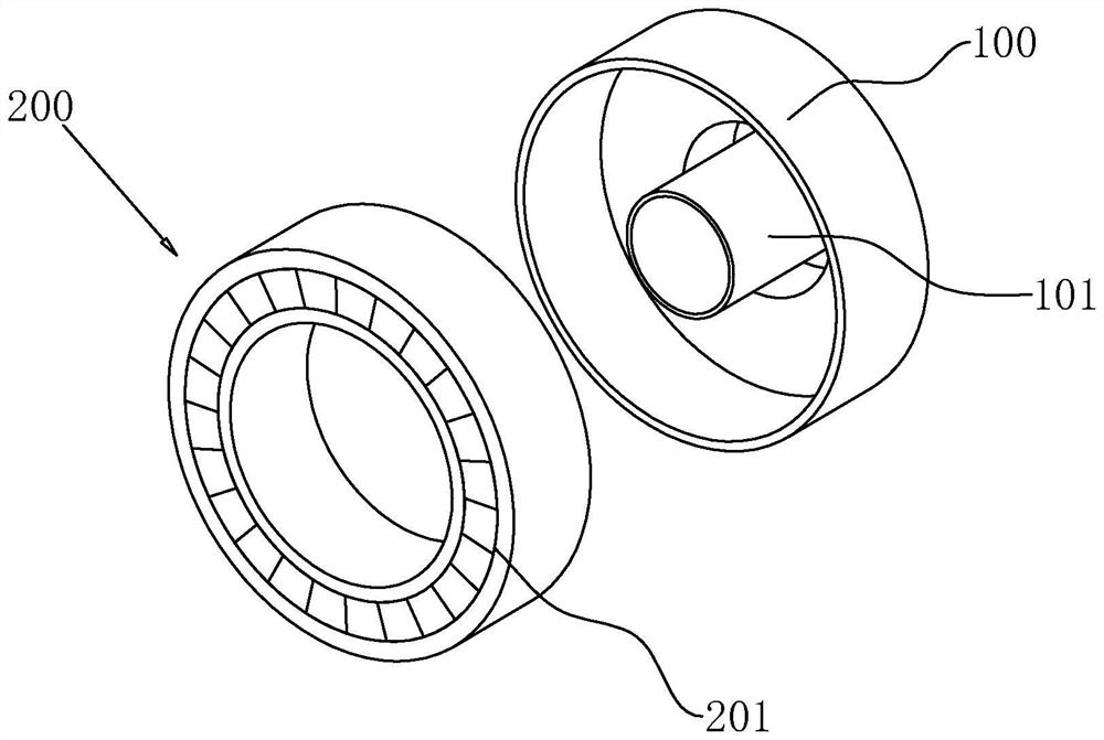
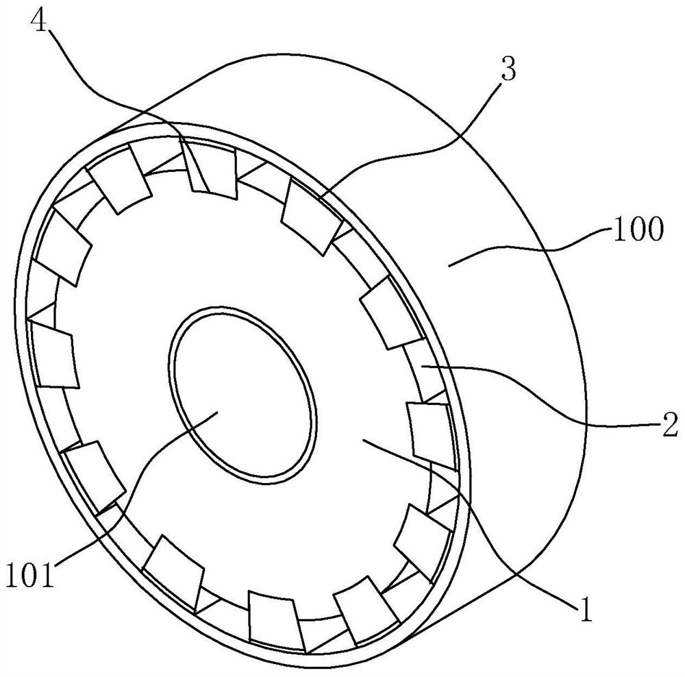
[0047] refer to image 3 , a splicing tool for permanent magnet AC servo motor magnetic steel, comprising a support 1, a number of limiters 2 and an adhesive layer 3, and a number of limiters 2 are arranged on the support 1 along the circumferential direction of the support 1, A receiving groove 4 is set between two adjacent limiting members 2 . During installation, the user places the support 1 in the rotor 100, makes the support 1 coaxial with the rotor 100, places the magnetic steel in the accommodating groove 4, and uses the adhesive layer 3 to glue the magnetic steel to the inner wall of the rotor 100. Then the user takes out the support 1 and the limiter 2 from the rotor 100, places the residual magnetic steel in the position where the limiter 2 is not taken out of the rotor 100, and uses the adhesive layer 3 to fix it to complete the installation .

[0048] refer to image 3, the support 1 is in the shape of a cylinder with an outer diameter smaller than the inner di...

Embodiment 2

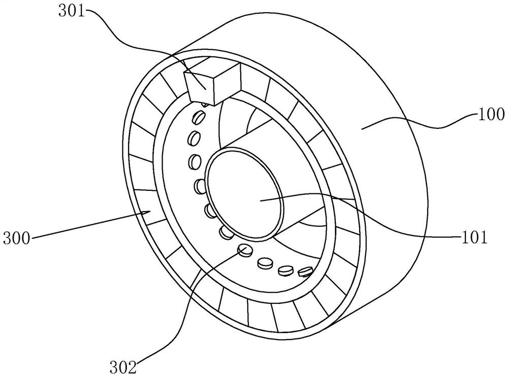
[0057] refer to Figure 4 , the main difference between this embodiment and Embodiment 1 is that a connecting member 5 is installed on one side of the support member 1, and the connecting member 5 is in the shape of a circular plate. When the user places the support member 1 in the rotor 100, the connecting member 5 is connected The part 5 is located on the side of the support part 1 away from the rotor 100. The edge of the connecting part 5 is provided with an avoidance groove 51 corresponding to the accommodating groove 4. The shape of the escape groove 51 is the same as that of the accommodating groove 4. Insert into the accommodating groove 4 through the escape groove 51 .

[0058] refer to Figure 4 and Figure 5 , all the limiting members 2 are slidably connected to the supporting member 1 on one side close to the supporting member 1, and are fixedly connected to the connecting member 5 at one end close to the connecting member 5. When all the magnetic steels are inser...


PUM


Abstract

The invention relates to a permanent magnet alternating current servo motor magnetic steel splicing tool and an installation method, and relates to the field of motor rotors, the permanent magnet alternating current servo motor magnetic steel splicing tool comprises a cylindrical support member used for bearing magnetic steel; the limiting pieces are arranged in the axial direction of the supporting piece, the multiple limiting pieces are arranged in the circumferential direction of the supporting piece at equal intervals, the width of the limiting pieces is the same as that of the magnetic steel, and a containing groove matched with the magnetic steel in shape is reserved between every two adjacent limiting pieces; and the bonding layer is used for bonding the magnetic steel and the rotating shaft. When a user inserts the magnetic steel into the accommodating groove, the accommodating groove can play an auxiliary positioning role on the magnetic steel, so that the magnetic steel can be always positioned at a correct position and is not easy to move due to the acting force of adjacent magnetic steel, and the consistency of electrical zero positions can be ensured; and after the magnetic steel in the accommodating groove and the rotor are adhered and fixed by the adhesive layer, a user pulls out the limiting piece and inserts the residual magnetic steel into the space between the adjacent magnetic steel in the rotor, so that the magnetic steel rotor has the effects of quick installation and relatively high convenience.

Description

technical field [0001] The invention relates to the field of motor rotors, in particular to a splicing tooling and an installation method for the magnetic steel of a permanent magnet AC servo motor. Background technique [0002] A Halbeck array is a special arrangement of magnets that can generate a strong magnetic field with relatively few magnets. The rotor of the motor is generally sleeved outside the stator, and the central shaft at the center is connected to the stator, and the Halbeck array is installed on the inner wall of the rotor, which can form a relatively good sine wave air gap magnetic density, and the formed magnetic field lines only diverge to one side, so There is no need to rely on magnetic conductive materials to form a closed magnetic circuit, and the structure can save space, thereby reducing the volume of the motor. [0003] refer to figure 1 At present, a commonly used installation method of the magnetic steel of the Haierbeck array in the motor shaf...

Claims


Application Information

Patent Timeline
IPC IPC(8): H02K15/03
CPCH02K15/03
Inventor 李尘唐开胜李娟
Owner 上海莘汭驱动技术有限公司
Why Eureka
Try Eureka