Automatic air leakage device and automatic air leakage method for full-area temperature sensing of bottle body

An all-area, automatic technology, applied in the container discharge method, container filling method, gas/liquid distribution and storage, etc., can solve the problems of inability to relieve pressure, large induction blind zone, explosion, etc.

Pending Publication Date: 2022-08-02
CHINA SPECIAL EQUIP INSPECTION & RES INST
View PDF0 Cites 0 Cited by
  • Summary
  • Abstract
  • Description
  • Claims
  • Application Information

AI Technical Summary

Problems solved by technology

For the temperature-driven safety relief device, since the temperature-driven safety relief device of the gas cylinder can only be installed at the mouth of the bottle, when the body of the gas cylinder is burned, due to the poor thermal conductivity of the gas cylinder, the safety relief at the mouth of the bottle will The temperature of the discharge device will not rise, so it cannot play the role of pressure relief
Therefore, for gas cylinders with plastic inner liner composite material or other gas cylinders whose temperature-driven safety relief device cannot sense the temperature during fire, when the cylinder body is exposed to fire, it is likely to explode, causing great danger
[0003]The temperature-driven safety release device in the prior art can only sense the temperature at the mouth of the bottle, and the temperature at other positions of the gas cylinder is its sensing blind zone. Big

Method used


Image

  • Automatic air leakage device and automatic air leakage method for full-area temperature sensing of bottle body
  • Automatic air leakage device and automatic air leakage method for full-area temperature sensing of bottle body
  • Automatic air leakage device and automatic air leakage method for full-area temperature sensing of bottle body

Examples


Embodiment 1

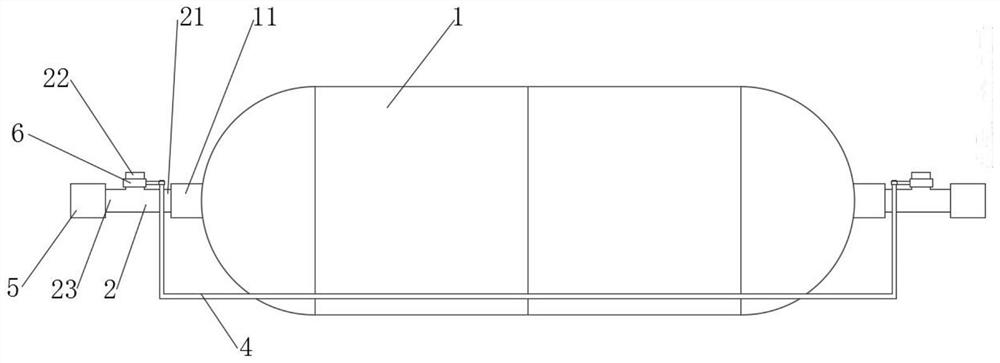
[0028] refer to figure 1 , 3 Shown is an automatic degassing device for temperature sensing in the whole area of ​​the bottle body. The device is communicated with the two bottle body openings 11 at the left and right ends of the gas bottle 1. The device includes: two air guide parts 2, two heat sensitive parts 3, Two heat-conducting members 4 , two valves 5 and two thermal resistance adjusting rings 6 . Wherein, each air guide 2 is provided with an air inlet 21 , a first air outlet 22 and a second air outlet 23 , and an air inlet 21 is communicated with a bottle body opening 11 for connecting the gas cylinder 1 The gas is injected into the two gas guides 2.

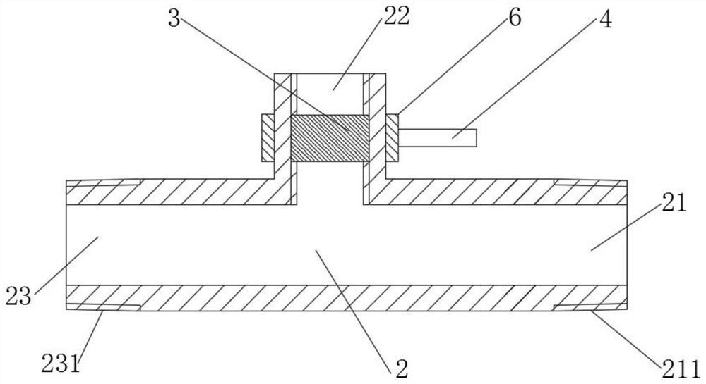
[0029] A heat-sensitive element 3 is embedded inside a first air outlet 22 , and a thermal resistance adjusting ring 6 is sleeved outside a first air outlet 22 . Two ends of the heat-conducting member 4 are respectively in contact with a first air outlet 22 , and the heat-conducting member 4 is used for transferring t...

Embodiment 2

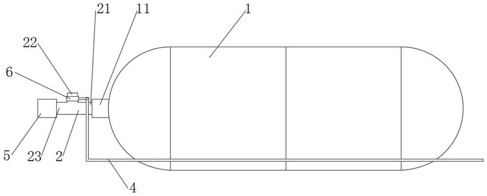
[0044] refer to figure 2 , 3 Shown is an automatic degassing device for temperature sensing in the whole area of ​​the bottle body. The device is communicated with the bottle body mouths 11 at the left and right ends of the gas bottle 1. And the thermal resistance adjustment ring 6 . The air guide 2 is provided with an air inlet 21, a first air outlet 22 and a second air outlet 23. The air inlet 21 communicates with the bottle body opening 11 and is used to inject the gas in the gas cylinder 1 into the air guide 2 in.

[0045] The heat-sensitive member 3 is embedded inside the first air outlet 22 ; one end of the heat-conducting member 4 is in conflict with the first air outlet 22 , and the other end is fitted with the outer wall of the gas cylinder 1 .

[0046] The heat conducting member 4 is used for transferring the heat near the gas cylinder 1 to the thermal resistance adjusting ring 6 . The thermal resistance adjusting ring 6 adjusts different thermal conductivity, t...


PUM


Abstract

The invention discloses an automatic gas releasing device and method capable of sensing temperature in all areas of a cylinder body, the device is communicated with a cylinder body opening of a gas cylinder, and the device comprises a gas guide part, a thermosensitive part and a heat conduction part; an air inlet, a first air outlet and a second air outlet are formed in the air guide piece; the air inlet is communicated with the bottle body opening; the thermosensitive part is embedded into the first air outlet; one end of the heat conducting piece is in contact fit with the first gas outlet, and the other end of the heat conducting piece is attached to the outer wall of the gas cylinder. According to the invention, the technical effects of full-area temperature monitoring and automatic air leakage of the bottle body can be realized.

Description

technical field [0001] The invention relates to the technical field of gas storage devices, and more particularly, to an automatic degassing device and an automatic degassing method for sensing temperature in the whole area of ​​a bottle body. Background technique [0002] When the gas cylinder is continuously burned, its internal gas pressure will increase, and at the same time, the strength of the gas cylinder body material will decrease, and the gas cylinder will explode after a period of combustion. Therefore, in order to avoid the above situation, a safety relief device will be installed on the valve of the gas cylinder to ensure that the gas in the cylinder can be discharged in time when the gas cylinder is burned to avoid explosion. At present, the safety relief devices on the mouth of the gas cylinder include a pressure-driven safety relief device and a temperature-driven safety relief device. The pressure-driven safety relief device includes bursting discs, safety ...

Claims


Application Information

Patent Timeline
Patent Type & Authority Applications(China)
IPC IPC(8): F17C13/02F17C13/04F17C13/12
CPCF17C13/026F17C13/04F17C13/12F17C2205/0332F17C2250/0439F17C2260/042Y02E60/32
Inventor 古纯霖黄强华李翔朱鸣薄柯赵保頔李介普张波刘易涛程亮崔栋梁王玲
Owner CHINA SPECIAL EQUIP INSPECTION & RES INST
Why Eureka
Try Eureka