Aerosol generating product with composite form plugging piece

An aerosol generation and aerosol generation technology, which is applied to tobacco and other directions, can solve the problems of low production efficiency, increased cost, inconvenience, etc., and achieve the effect of improving efficiency

Pending Publication Date: 2022-08-05
CHINA TOBACCO YUNNAN IND
View PDF0 Cites 0 Cited by
  • Summary
  • Abstract
  • Description
  • Claims
  • Application Information

AI Technical Summary

Problems solved by technology

The problems of the above-mentioned filling preparation method are: 1. When filling, the pipe is placed vertically, and the positions of the sealing parts and filter parts on both sides of the cavity are difficult to locate, and the problem of inconsistent axial lengths of the cavity sections of different samples is likely to occur; 2. The outer surface of the blocking piece and the filter piece and the inner wall of the paper tube are fixed only by friction, and the blocking piece and the filter piece are easily displaced to the cavity section during transportation, or the filter piece is partially sucked out of the outer tube during the suction process; 3. Filling The limited method can

Method used


Image

  • Aerosol generating product with composite form plugging piece
  • Aerosol generating product with composite form plugging piece
  • Aerosol generating product with composite form plugging piece

Examples


Example Embodiment

[0079] Example 1

[0080] The present embodiment prepares a multi-stage aerosol generating product according to preparation method 2, which comprises the following steps:

[0081] Step 1, the preparation of the mouth stick:

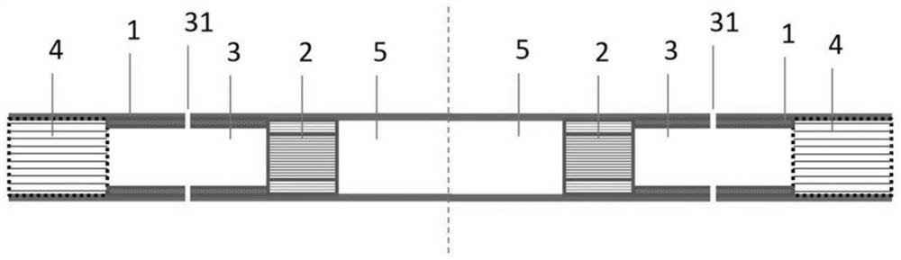
[0082] The blocking element 2 and the filter element 4 are wrapped by the outer pipe 1, the blocking element 2 and the filter element 4 are spaced apart by a first axial length, and the length is defined by the outer pipe 1 to define the cavity section 3,

[0083] One end of the blocking member 2 away from the cavity section 3 is defined by the outer tube 1 to define an aerosol-generating matrix containing cavity 5;

[0084] Step 2, the filling of the aerosol generating material:

[0085] The nozzle rod is in a vertical vertical state, that is, a state vertical to the horizontal plane, wherein the aerosol generation substrate accommodating cavity 5 is vertically upward, and the flowing aerosol generation material is squeezed into the aerosol generation ...

Example Embodiment

[0105] Example 2

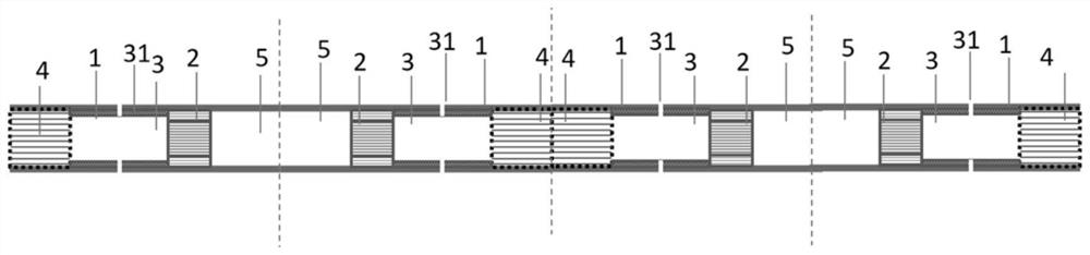
[0106] In this embodiment, a multi-stage aerosol generating product is prepared according to preparation method 2. The difference between this embodiment and embodiment 1 is: 1. In step 1, the nozzle rod can be divided into 4 nozzle rods, and the 4 nozzle rods pass through The filter element 4 is connected with the aerosol-generating substrate accommodating cavity 5; at this time, there is also a slitting step between step 1 and step 2, and the connected filter element 4 and the connected aerosol-generating matrix accommodating cavity 5 are cut to separate the mouth The stick is cut into 4 mouth sticks. The axial length of the filter element at the connection point is twice the axial length of the filter element in a single nozzle stick. Similarly, the axial length of the aerosol-generating matrix accommodating cavity reserved at the connection point is the aerosol generation in a single nozzle stick. The matrix contains twice the axial length of the cavity...

Example Embodiment

[0107] Example 3

[0108] In this embodiment, a multi-stage aerosol generating product is prepared according to preparation method 1, and the structure of the blocking member in the aerosol generating product is the same as that in embodiment 1, which includes the following steps:

[0109] Step 1, the preparation of the mouth stick:

[0110] The blocking element 2 and the filter element 4 are wrapped by the outer pipe 1, the blocking element 2 and the filter element 4 are spaced apart by a first axial length, and the length is defined by the outer pipe 1 to define the cavity section 3,

[0111] One end of the blocking member (2) away from the cavity section 3 is defined by the outer tube 1 to define an aerosol-generating matrix containing cavity 5;

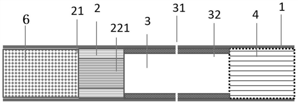
[0112] Step 2, filling of the aerosol generation substrate 6:

[0113] The nozzle bar is in a vertical state, that is, a state perpendicular to the horizontal plane, wherein the aerosol-generating substrate accommodating chamber...


PUM


Abstract

The aerosol generating product comprises an integrated outer tube (1), and an aerosol generating substrate (6), a plugging piece (2), a cavity structure (3) and a filtering piece (4) which are positioned in the outer tube (1), the plugging piece (2) comprises a pipe wall (21) and a pipe cavity (22), the pipe wall (21) is of a groove corrugated structure and comprises an outer layer (211), an inner layer (212) and a groove corrugated layer (213) located between the outer layer (211) and the inner layer (212), the outer surface of the plugging piece (2) is limited by the outer layer (211), and the pipe cavity (22) is limited by the inner layer (212); a gathering sheet bar (221) is arranged in the pipe cavity (22). In the smoking process, the gathering sheet bar shrinks after being heated to block part of the middle airflow, so that more aerosol is in contact with aroma enhancing substances and/or fuming substances on the groove corrugated layer (213), and the effects of aerosol aroma supplementing and smoke amount increasing are further improved.

Description

technical field [0001] The invention relates to the technical field of heat-not-burn cigarettes, in particular to an aerosol-generating product with a composite-form blocking member. Background technique [0002] As consumers pay more attention to health issues and increase their demand for personalized experience of cigarette products, the tobacco industry has continuously responded to the upgrading of consumers' needs and developed various smoking products with reduced scorch and harm reduction. Among them, heated cigarettes can provide a healthier smoking experience while satisfying consumers' sensory requirements for cigarette products because of their different heating methods from traditional cigarette products. [0003] Existing one-piece aerosol-generating articles include an outer tube, an aerosol-generating matrix filled in the outer tube, and other cooling and aerosol-circulating units. At present, the aerosol-generating substrate of the integrated aerosol-genera...

Claims


Application Information

Patent Timeline
IPC IPC(8): A24F40/70A24F40/40A24F40/20
CPCA24F40/70A24F40/40A24F40/20
Inventor 赵杨李雪梅秦云华杨柳者为张建荣段沅杏向能军龚为民夏建军申钦鹏雷萍李世卫巩效伟郭丁荣
Owner CHINA TOBACCO YUNNAN IND
Why Eureka
Try Eureka