Building waste recovery equipment based on construction cost control

A technology for construction waste and recycling equipment, which is applied in construction waste recycling, recycling technology, solid waste management and other directions, can solve the problems of saving time and cost of sand screening, inconsistent size, and inability to automatically separate metal objects, so as to save screening sand. time cost effect

Pending Publication Date: 2022-08-05
林环周
View PDF0 Cites 0 Cited by
  • Summary
  • Abstract
  • Description
  • Claims
  • Application Information

AI Technical Summary

Problems solved by technology

[0003] However, the current construction waste recycling equipment only crushes the construction waste, which can be recycled to the base of the road pavement, used to prepare waste materials such as recycled concrete or pile foundation filler, and the waste needs to be crushed and the particle size used is inconsistent. The sand needs to be screened again, and it cannot be recycled according to the

Method used


Image

  • Building waste recovery equipment based on construction cost control
  • Building waste recovery equipment based on construction cost control
  • Building waste recovery equipment based on construction cost control

Examples


Embodiment 1

[0034] Example 1: Please refer to Figure 1 to Figure 9 :

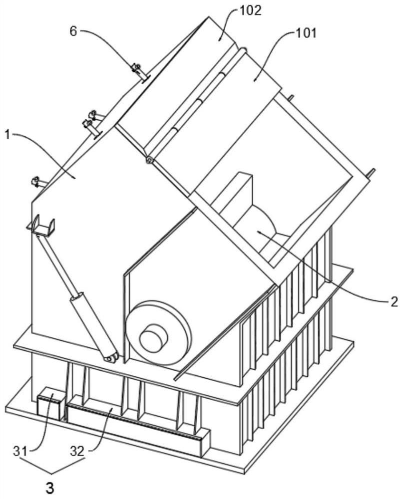
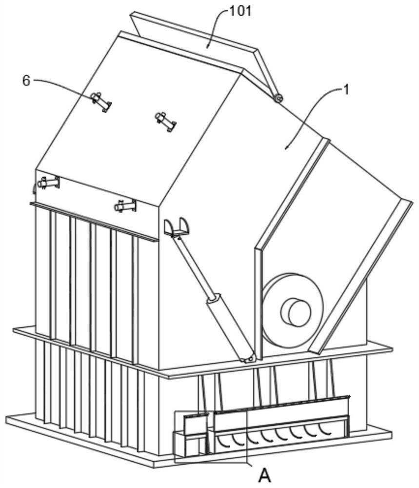
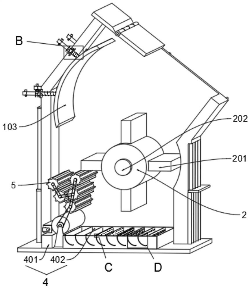
[0035] The present invention proposes a construction waste recycling device based on construction cost control, comprising: a main body 1; a rotor 2 is movably connected inside the main body 1; the outer left bottom surface of the main body 1 is fixedly connected to a sealing box group 3; The box group 4, the gear group 5 and the magnet wheel 7 are installed inside the main body 1, and the upper part of the main body 1 is movably connected to the counterattack plate 103 through the hanger 6; the sealed box group 3 includes a small outer box 31 and a large outer box 32; The box group 4 includes a metal box 401 and a powder box 402, and the left outer end of the metal box 401 is placed inside the small outer box 31, and the left outer end of the powder box 402 is placed inside the large outer box 32; the rear side of the magnet wheel 7, the main body 1. The scraper 8 is fixedly connected internally; the front side of t...

Embodiment 2

[0045] On the basis of the first embodiment, a sealing cover can be added to the top of the main body 1, and an atomizer can be added to the bottom of the sealing cover. 1. The air at the top feed is physicochemically treated to reduce the outward flow of dust and avoid environmental pollution.

[0046] The specific usage and function of this embodiment: In the present invention, when the waste material enters the interior from the top of the main body 1, all the waste material will be dumped above the rotor 2 due to the difference in angle, and will not fall off the front side of the baffle 201. After the rotor 2 rotates, the waste is driven upwards and flipped by the baffle 201 to achieve impact crushing;

[0047] When the magnet wheel 7 rotates with the linkage shaft 701 , the gear set 5 is driven to rotate by the batch machine, so that the scrap particles falling from the rear side of the rotor 2 are further smashed through the gear set 5 , and the metal objects in it are ...


PUM


Abstract

The invention provides building waste recovery equipment based on construction cost control, and relates to the technical field of building waste recovery equipment. The bottom surface of the left side outside the main body is fixedly connected with the sealing box group; the storage box group is placed on the bottom surface inside the main body; the sealing box group comprises a small outer box and a large outer box; the storage box set comprises a metal box and a powder box, the outer end of the left side of the metal box is arranged in the small outer box, the outer end of the left side of the powder box is arranged in the large outer box, after the sliding rod drives the screening plate to slide in the sliding way with the shaft as the circle center, the screening plate pokes powder smashed in the powder box to the front side, screening holes of the screening plate are gradually enlarged from back to front, and the powder is smashed. The powder is separated in the shifting process from back to front, the larger the particles are, the larger the particles are, the larger the particles are, the powder is shifted forwards, the powder in the powder box is separated, follow-up recycling according to the particle sizes is facilitated, the sand screening time cost is saved, and the problem that recycling cannot be conducted according to the particle sizes, and the time cost is saved is solved.

Description

technical field [0001] The invention relates to the technical field of construction waste recycling equipment, in particular to a construction waste recycling equipment based on construction cost control. Background technique [0002] Construction wastes such as muck and reinforced concrete fragments will be generated during the construction, laying, demolition and repair of buildings. In order to reduce the pollution and damage to air and water resources caused by construction wastes, it is necessary to recycle construction wastes. [0003] However, the current construction waste recycling equipment only smashes construction waste, which can be recycled for use in road pavement bases, for preparing recycled concrete or pile foundation fillers and other wastes. The waste needs to be pulverized and the particle size used is inconsistent. It needs to be screened again for sand treatment, which cannot be recycled according to the particle size, saving the time and cost of sand ...

Claims


Application Information

Patent Timeline
IPC IPC(8): B09B3/35B09B5/00
CPCB09B3/35B09B5/00Y02W30/91
Inventor 林环周
Owner 林环周
Why Eureka
Try Eureka