Welding robot capable of automatically and circularly cleaning track and blocking and guiding foreign matters

A welding robot and clean technology, applied in welding equipment, auxiliary welding equipment, welding/cutting auxiliary equipment, etc., can solve the problems of falling into paint, enlargement, wear and vibration of welding robot rotating parts, and achieve the effect of preventing loss.

Pending Publication Date: 2022-08-05
王紫琪
0 Cites 0 Cited by

AI-Extracted Technical Summary

Problems solved by technology

[0003] When the existing welding robot welds some long workpieces, due to the poor welding site environment, a large amount of welding dust will be attached to the rack on the support track, and when the welding robot moves back and forth on the track, it will cause Welding dust adheres to the transmission parts inside the welding robot, which will cause the wear and tear of the rotating parts or increase the vibration of the welding...

Abstract

The invention relates to the field of welding equipment, in particular to a welding robot capable of automatically and circularly cleaning a rail and blocking and guiding foreign matters, which comprises a support sliding device, the support sliding device is slidably sleeved on the top end of a support frame body, and a welding arm is fixedly mounted in the center of the outer side of the support sliding device. The auxiliary cleaning device is fixedly installed at the top end of the supporting sliding device, the transmission device and the cleaning and lubricating device are fixedly installed on the inner side of the supporting sliding device, and the cleaning and lubricating device is located above the transmission device. And the transmission device comprises teeth, a contact extrusion block, an output motor, a first gear, a conical collection cavity, a first conical gear and a sealing cover, and the first gear is fixedly mounted at the bottom end of the output motor. And through the arrangement of the transmission device, the cleaning and lubricating device and the auxiliary cleaning device, transmission parts in the welding robot can be lubricated, and the paint surface of the welding robot can be cleaned.

Application Domain

Welding/cutting auxillary devicesAuxillary welding devices +2

Technology Topic

Electric machineryEngineering +4

Image

  • Welding robot capable of automatically and circularly cleaning track and blocking and guiding foreign matters
  • Welding robot capable of automatically and circularly cleaning track and blocking and guiding foreign matters
  • Welding robot capable of automatically and circularly cleaning track and blocking and guiding foreign matters

Examples

  • Experimental program(1)

Example Embodiment

[0025] In order to make it easy to understand the technical means, creation features, achieved goals and effects of the present invention, the present invention will be further described below with reference to the specific embodiments.
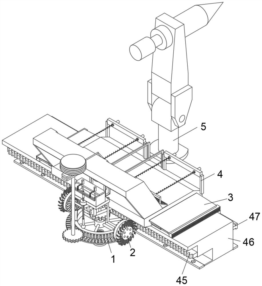
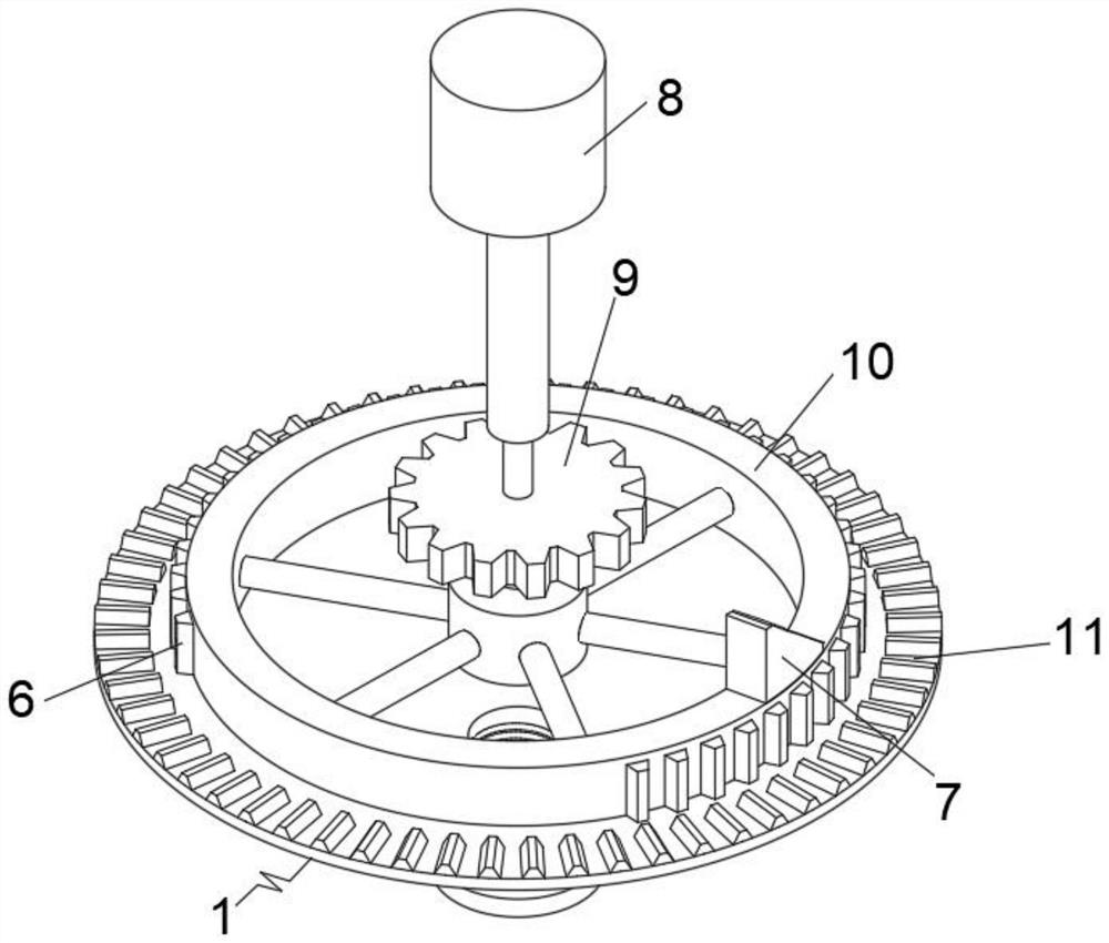
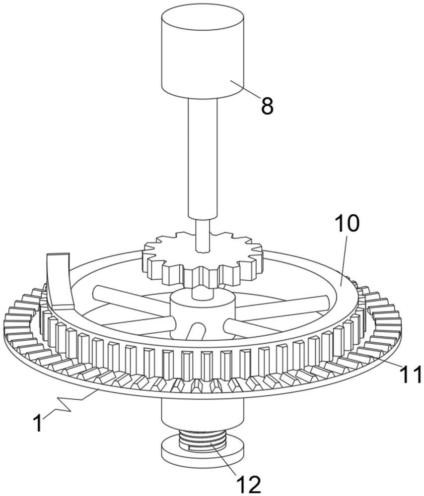
[0026] like Figure 1-Figure 8 As shown, a welding robot according to the present invention that can perform automatic orbital cleaning and foreign object blocking and diversion functions includes a supporting sliding device 3, which is slidably sleeved on the top of the supporting frame body 46, and the welding arm 5 is fixedly installed on the outer center of the supporting sliding device 3, the auxiliary cleaning device 4 is fixedly installed on the top of the supporting sliding device 3, the transmission device 1 and the cleaning and lubricating device 2 are respectively fixedly installed on the inner side of the supporting sliding device 3, and the cleaning and lubricating device 2 is located above the transmission 1.
[0027]Preferably, the transmission device 1 includes teeth 6, a contact extrusion block 7, an output motor 8, a first gear 9, a conical collecting cavity 10, a first conical gear 11 and a cover 12, and the first gear 9 is fixedly installed At the bottom end of the output motor 8, the conical collecting cavity 10 is fixedly installed on the bottom end of the first gear 9, the contact pressing block 7 is fixedly installed on the top outer ring of the conical collecting cavity 10, and the teeth 6 are fixedly installed on On the outer ring of the conical collection cavity 10, and the teeth 6 are located below the contact pressing block 7, the first bevel gear 11 is fixedly installed on the outer ring of the conical collection cavity 10, and the first bevel gear 11 Below the teeth 6, the cover 12 is screwed into the center of the bottom end of the conical collecting cavity 10, and meshes with the second gear 28 and the second bevel gear 24 through the teeth 6 and the first bevel gear 11 respectively , so that while the first gear 9 is rotating, it can drive the winding wheel 26 and the second bevel gear 24 to rotate synchronously, so as to perform the cleaning of the winding of the connecting rope 44 and the nylon brush handle 13 .
[0028] Preferably, the cleaning and lubricating device 2 includes a nylon brush handle 13, an L-shaped moving insert rod 14, a first support sleeve 15, a first return spring 16, a plastic sealing plug 17, an oil storage cavity 18, an L-shaped support rod 19, The drip head 20 , the communication pipe 21 , the contact cross frame 22 , the moving guide rod 23 , the second bevel gear 24 and the support base plate 25 , the support base plate 25 is fixedly installed on the bottom end of the oil storage chamber 18 , and the L-shaped support rod 19 Symmetrically and fixedly installed on the bottom end of the support base plate 25, the second bevel gear 24 is rotatably installed on the end of the L-shaped support rod 19 away from the support base plate 25, and the nylon brush handle 13 is fixedly installed on the second bevel gear 24 away from the L-shaped support On the side end surface of the rod 19, the first support sleeve 15 is symmetrically and fixedly installed on the top end of the oil storage cavity 18, the first return spring 16 is fixedly installed on the inner top of the first support sleeve 15, and the L-shaped movable insertion rod 14 It is fixedly installed at the bottom end of the first return spring 16, the plastic sealing plug 17 is fixedly installed at the bottom end of the L-shaped moving plunger 14, and the drip head 20 is fixedly installed at the bottom end of the communication tube 21, which symmetrically penetrates the support base plate. 25 is fixedly installed at the bottom end of the oil storage chamber 18 , the moving guide rod 23 is slidably inserted into the side end of the support base plate 25 away from the L-shaped support rod 19 , and the contact cross frame 22 is fixedly installed on the top of the moving guide rod 23 , When the moving guide rod 23 moves upward, it can drive the contact cross frame 22 to squeeze the L-shaped moving insert rod 14 to move upward, so that the plastic sealing plug 17 can be taken out from the interior of the communication pipe 21 upward, resulting in the oil storage cavity 18 The lubricating oil inside flows to the inside of the drip head 20 to facilitate lubrication of the first gear 9 and the rail rack 45 .
[0029] Preferably, the support sliding device 3 includes a winding wheel 26, a connecting rod 27, a second gear 28, an oblique grid baffle 29, a second support sleeve 30, a second return spring 31, a moving round rod 32, and a contact protection edge The bar 33, the auxiliary guide top plate 34, the storage and placement slot 35, the support sliding plate 36, the L-shaped limit guide rod 37 and the sliding guide slot 38, the storage and placement slot 35 is opened inside the two ends of the support sliding plate 36, and the auxiliary guide top plate 34 It is slidably inserted into the storage and placement slot 35, the contact protection edge 33 is fixedly installed on the bottom end of the auxiliary guide top plate 34 away from the storage slot 35, and the moving round rod 32 is symmetrically and fixedly installed on the contact protection edge 33 close to the supporting sliding plate 36. On one side, the second return spring 31 is fixedly installed between the moving round rod 32 and the second support sleeve 30, and the second support sleeve 30 is fixedly installed at the bottom of both ends of the support sliding plate 36, obliquely blocking The plate 29 is fixedly installed on the top rear end of the supporting sliding plate 36 , the L-shaped limit guide rod 37 is fixedly installed at the top front end of the supporting sliding plate 36 equidistantly, and the connecting rod 27 is rotatably installed on the rear end top of the inclined grid baffle plate 29 , the winding wheel 26 and the second gear 28 are fixedly installed on the top and bottom ends of the connecting rod 27, respectively, and the supporting cross bar 39 is opened on the inner side of the front end of the supporting sliding plate 36. When the second return spring 31 maintains a normal state, the circular rod moves 32 drives the contact protection edge strip 33 to be in a state of being extruded outward, so that the support sliding plate 36 can be prevented from strongly colliding with external objects. This makes it possible to prevent external welding slag from falling into the area between the support sliding plate 36 and the contact protection edge 33 .
[0030] Preferably, the auxiliary cleaning device 4 includes a support cross bar 39, a push shovel plate 40, a third return spring 41, a U-shaped support frame 42, a positioning sleeve 43 and a connecting rope 44. The positioning sleeve 43 is symmetrically and fixedly installed on the U-shaped support On the top of the frame 42, the third return spring 41 is fixedly installed inside the rear end of the positioning sleeve 43, the support cross bar 39 is fixedly installed on the end of the third return spring 41 away from the positioning sleeve 43, and pushes the shovel plate 40 to be fixedly installed in the position. The bottom end of the support crossbar 39, the connecting rope 44 is fixedly connected to the center of one end of the support crossbar 39 away from the U-shaped support frame 42, when the connecting rope 44 is in a relaxed state, the elasticity of the third return spring 41 can drive the push The shovel plate 40 quickly moves in the direction of the U-shaped support frame 42 to complete the reset work of pushing the shovel plate 40 .
[0031] Preferably, the output motor 8 and the supporting bottom plate 25 are respectively fixedly installed inside the rear end of the supporting sliding plate 36, and the supporting bottom plate 25 is located at the rear end of the output motor 8, and the second bevel gear 24 meshes with the first bevel gear 11, The nylon brush handle 13 is in contact with the surface of the rail rack 45, the support sliding plate 36 and the contact protection edge 33 are both slidably clamped on the top end of the support frame body 46, and the sliding guide groove 38 is slidably sleeved on the sliding key 47 to move. The bottom end of the guide rod 23 is in contact with the top end of the outer ring of the conical collecting cavity 10, the second gear 28 is engaged with the teeth 6, and the end of the connecting rope 44 away from the support cross bar 39 is fixedly installed on the winding wheel 26, the first The gear 9 is engaged with the track rack 45, and the first gear 9 is in contact with the track rack 45, so that the transmission device 1, the cleaning and lubricating device 2, the supporting sliding device 3, the auxiliary cleaning device 4 and the welding arm 5 can be driven to move, and at the same time , the conical collecting cavity 10 is fixedly installed on the bottom end of the first gear 9, so that the first gear 9 can drive the conical collecting cavity 10 to rotate at the same time, so as to complete the multi-directional transmission work.
[0032] Preferably, the top end of the contact pressing block 7 is provided with a 45° slope, the interior of the conical collection cavity 10 is provided with a circular arc slope from top to bottom, the surface of the cover 12 and the center of the bottom end of the conical collection cavity 10 There are mutually compatible threads, the rear side of the first support sleeve 15 is provided with a chute that matches the L-shaped moving insert rod 14 , the diameter of the outer ring of the plastic sealing plug 17 is the same as the diameter of the inner ring of the communication pipe 21 Equally, the interior of the oil storage chamber 18 is set in a hollow state, and the oil storage chamber 18 communicates with the communication pipe 21, and the top of the outer end of the supporting sliding plate 36 away from the inclined lattice baffle plate 29 is arranged at a 45° slope, and the conical collection The distribution angle of the teeth 6 on the side end of the outer ring of the cavity 10 is 270°, and the tops of the auxiliary guide top plate 34 and the pushing shovel plate 40 are set at a slope of 45°. The upper setting distribution angle is 270°, so that after the conical collecting cavity 10 rotates three quarters of a turn, the teeth 6 will be disconnected from the second gear 28, causing the second gear 28 to lose the meshing force, which is convenient for the third return spring 41 pulls the connecting rope 44 and the take-up wheel 26 to rotate and reset.
[0033]Working principle: When in use, first add lubricating oil to the inside of the oil storage cavity 18, then start the output motor 8 to drive the first gear 9 to rotate, and the first gear 9 meshes with the rail rack 45, so that the The transmission device 1, the cleaning and lubricating device 2, the supporting sliding device 3, the auxiliary cleaning device 4 and the welding arm 5 move, so that the welding arm 5 can move the welding work. At this time, the conical collecting cavity 10 is fixedly installed on the first gear 9, and the first bevel gear 11 is fixedly installed at the bottom of the outer ring of the conical collecting cavity 10, so that the conical collecting cavity 10 can drive the first bevel gear 11 to rotate while the conical collecting cavity 10 is rotating. A bevel gear 11 meshes with the second bevel gear 24, so that when the first bevel gear 11 rotates, it can drive the second bevel gear 24 to rotate at the same time, and the nylon brush handle 13 is fixedly mounted on the second bevel gear 24. and the nylon brush handle 13 is in contact with the inner surface of the track rack 45, so that when the nylon brush handle 13 rotates, the welding dust attached to the surface of the track rack 45 can be swept away. The pressing block 7 is fixedly installed on the top of the outer ring of the conical collecting cavity 10, and when the first return spring 16 remains in a normal state, it squeezes the L-shaped moving insert rod 14, the plastic sealing plug 17, the contact cross frame 22 and the moving guide rod 23 keeps moving downward, so that the bottom end of the moving guide rod 23 is always in contact with the top end of the outer ring of the conical collecting cavity 10. At this time, when the conical collecting cavity 10 drives the contact pressing block 7 and the moving guide rod 23 When the bottom end is in contact, the top end of the contact pressing block 7 is set at a 45° slope, so that the contact pressing block 7 can squeeze the moving guide rod 23 to move upward. 14 are vertically aligned, so that when the contact cross frame 22 moves upward, it can drive the L-shaped moving plunger 14 and the plastic sealing plug 17 to move upward, causing the first return spring 16 to compress upward, and at the same time, the plastic sealing plug 17 will Take out the inside of the pipe 21, the lubricating oil in the oil storage chamber 18 will flow downward from the inside of the communication pipe 21 until it flows out from the inside of the drip head 20. At this time, the bottom end of the drip head 20 is facing the rail. between the rack 45 and the first gear 9 , so that lubricating oil can be filled between the rail rack 45 and the first gear 9 to improve the degree of lubrication between the rail rack 45 and the first gear 9 , and at the same time , when the conical collecting cavity 10 drives the contact extrusion block 7 to pass the bottom end of the moving guide rod 23, the L-shaped moving insert rod 14 and the plastic sealing plug 17 can be driven downward rapidly by the elasticity of the first return spring 16. Move until the plastic sealing plug 17 is inserted into the communication pipe 21 again, so as to prevent the lubricating oil in the oil storage cavity 18 from flowing out too much. When the collecting cavity 10 rotates, it can drive the second gear 28 to rotate at the same time, and is fixedly installed on the top of the second gear 28 through the connecting rod 27, and the winding wheel 26 is fixedly installed on the top of the connecting rod 27, so that the second gear is fixed on the top of the connecting rod 27. 28 When rotating, it can drive the rewinding wheel 26 At the same time, it rotates and is fixedly installed on the winding wheel 26 through the connecting rope 44, so that when the winding wheel 26 rotates, the connecting rope 44 can be pulled to wind up on the winding wheel 26. At this time, it is fixed and installed through the supporting cross bar 39 On the connecting rope 44, when the rewinding wheel 26 rotates, the support cross bar 39 can be pulled to move in the direction of the oblique grid baffle 29. At this time, the shovel plate 40 is fixedly installed on the bottom of the support cross bar 39 by pushing the shovel plate 40. and the bottom end of the push shovel plate 40 is in contact with the top surface of the supporting sliding plate 36, so when the pushing shovel plate 40 moves, the welding slag attached to the top surface of the supporting sliding plate 36 can be scraped off. The three return springs 41 are fixedly installed between the support crossbar 39 and the positioning sleeve 43, and the positioning sleeve 43 is fixedly installed on the U-shaped support frame 42, and the U-shaped support frame 42 is fixedly installed on the support sliding plate 36 away from the inclined grid The top of the baffle plate 29, therefore, when the support cross bar 39 moves in the direction of the oblique grid baffle plate 29, the third return spring 41 can be pulled to extend the length. The distribution angle of the teeth 6 is 270°, so that after the conical collecting cavity 10 rotates by 270°, the teeth 6 will be disconnected from the second gear 28, causing the second gear 28 to lose the meshing force. The elasticity of the three return springs 41 can drive the support cross bar 39 to move quickly in the direction of the U-shaped support frame 42 until the support cross bar 39 and the U-shaped support frame 42 are attached again, so that the push shovel plate 40 can be quickly reset, It is convenient to carry out the work of scraping the welding slag at the top of the supporting sliding plate 36 again. When the supporting sliding plate 36 moves, it is symmetrically and fixedly installed on both ends of the supporting sliding plate 36 through the second supporting sleeve 30, and the second return spring 31 is fixedly installed at the two ends of the supporting sliding plate 36. Between the second support sleeve 30 and the moving round rod 32 , and the moving round rod 32 is slidably inserted into the second support sleeve 30 , the contact protection edge 33 can be brought into contact with the welding slag on the support sliding plate 36 in advance , so that the welding slag can be pushed forward to prevent the support sliding plate 36 from directly contacting the welding slag. At the same time, through the elasticity of the second return spring 31, when the contact protection edge 33 is in contact with the outer track edge, the supporting sliding plate can be reduced. The impact force between 36 and the edge of the track increases the service life of the supporting sliding plate 36. When the device is in use, it is slidably sleeved on the sliding key 47 through the sliding guide groove 38, so that the supporting sliding plate 36 can be prevented from being skewed when moving. phenomenon, the auxiliary guide top plate 34 is fixedly installed on the top of the contact protection edge 33, and when the contact protection edge 33 moves, the auxiliary guide top plate 34 can be driven to slide inside the storage slot 35, so that external welding slag can be avoided. The top of the supporting frame body 46 between the contact protection edge 33 and the supporting sliding plate 36 falls on the top of the supporting frame body 46, and the top of the auxiliary guiding top plate 34 is arranged with a 45° slope, so that welding slag can be prevented from accumulating on the top of the auxiliary guiding top plate 34, When the device is in use, the conical collecting cavity 10 is located directly below the communicating tube 21 and the drip head 20, and the interior of the conical collecting cavity 10 is arranged with a circular arc slope from top to bottom, so that it can be accessed from the The lubricating oil dropped between the orbital rack 45 and the first gear 9, meanwhile, by screwing out the cover 12 from the center of the bottom end of the conical collecting cavity 10, the inside of the conical collecting cavity 10 can be discarded The lubricating oil is poured to avoid the accumulation of excessive lubricating oil in the conical collecting cavity 10 .
[0034] The foregoing has shown and described the basic principles, main features and advantages of the present invention. Those skilled in the art should understand that the present invention is not limited by the above-mentioned embodiments, and the descriptions in the above-mentioned embodiments and the description are only to illustrate the principle of the present invention. Without departing from the spirit and scope of the present invention, the present invention will also There are various changes and improvements which fall within the scope of the claimed invention. The claimed scope of the present invention is defined by the appended claims and their equivalents.

PUM

no PUM

Description & Claims & Application Information

We can also present the details of the Description, Claims and Application information to help users get a comprehensive understanding of the technical details of the patent, such as background art, summary of invention, brief description of drawings, description of embodiments, and other original content. On the other hand, users can also determine the specific scope of protection of the technology through the list of claims; as well as understand the changes in the life cycle of the technology with the presentation of the patent timeline. Login to view more.

Similar technology patents

Method for quickly harvesting bag material planted Chinese yam chips

InactiveCN109744115Afast harvestavoid churn
Owner:GUANGXI ZHUANG AUTONOMOUS REGION ACAD OF AGRI SCI

Environment-friendly aquaculture feed easy to eat

InactiveCN106071380Aavoid churnreduce pollution
Owner:ANQING FUJIANG FISHERIES BREEDING CO LTD

Water quality improver for culture pond and preparation method of water quality improver

PendingCN113697923Aavoid churnImprove biological activity and utilization
Owner:陵水晨海种业有限公司

Method for implementing legal listening

InactiveCN101047567Aavoid churn
Owner:刘小清

Classification and recommendation of technical efficacy words

Why Eureka
Try Eureka