Numerically-controlled machine tool with material guide channel

A technology of CNC machine tools and material guides, which is applied to the parts of grinding machine tools, grinding machines, manufacturing tools, etc. It can solve the problems of workpiece collision, inconvenient positioning of workpiece blanks, wear and other problems, and achieve the effect of preventing wear and smooth conveying

Pending Publication Date: 2022-08-05
张凯
View PDF6 Cites 0 Cited by
  • Summary
  • Abstract
  • Description
  • Claims
  • Application Information

AI Technical Summary

Problems solved by technology

[0005] A numerical control machine tool with a material guide, comprising a main body of the numerical control machine tool, the main body of the numerical control machine tool is composed of a control device, a grinding mechanism and an operating table, the right bottom end of the control device is welded to the left side of the operating table connected, the grinding mechanism is set above the console, the upper surface of the console is provided with a positioning mechanism, the right side of the console is welded with a guideway, and the right side of the guideway is fixedly installed with A receiving mechanism, the receiving mechanism includes a material receiving box and a load-bearing pressure-releasing assembly, the load-bearing and pressure-releasing assembly includes a compression-resistant elastic casing, and the inside of the compression-resistant elastic casing is provided with an elastic receiving strip and a pressure-releasing elastic The right side of the control device is fixedly equipped with a hydraulic device and a lifting plate on the left side of the positioning mechanism. The cooperating use of related accessories of the mechanism solves the problem that the workpiece is prone to collision and wear due to the inclined setting of the guide channel when guiding the material, and the problem that the workpiece blank is not easy to position during processing

Method used


Image

  • Numerically-controlled machine tool with material guide channel
  • Numerically-controlled machine tool with material guide channel
  • Numerically-controlled machine tool with material guide channel

Examples


Embodiment 1

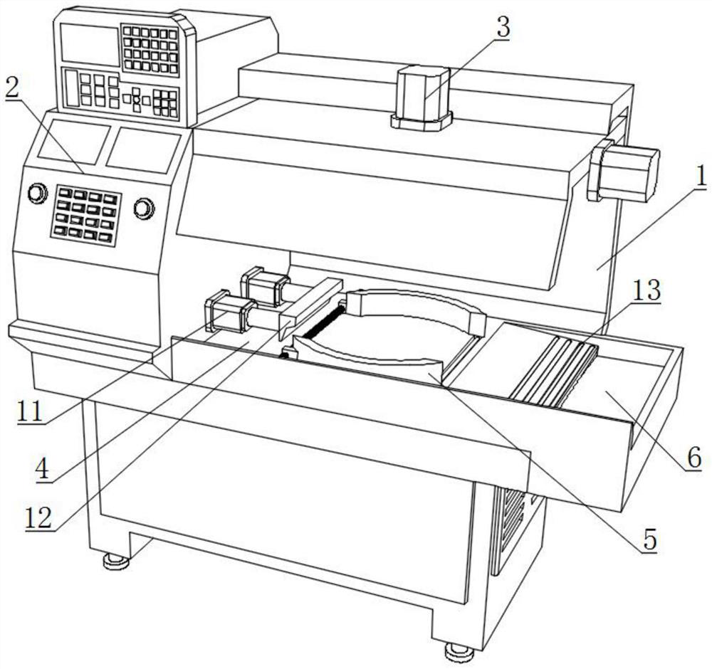
[0029] like Figure 1-6 As shown, the present invention provides a CNC machine tool with a material guide, including a CNC machine tool main body 1, the CNC machine tool main body 1 is composed of a control device 2, a grinding mechanism 3 and an operating table 4, and the right bottom end of the control device 2 is connected to the The left side of the operating table 4 is connected by welding, the grinding mechanism 3 is arranged above the operating table 4, the upper surface of the operating table 4 is provided with a positioning mechanism 5, and the right side of the operating table 4 is welded with a material guide 13, which guides the A receiving mechanism 6 is fixedly installed on the right side of the material channel 13. The receiving mechanism 6 includes a material receiving box 61 and a load-relief assembly 62. The load-relief assembly 62 includes a pressure-resistant elastic sleeve 621. An elastic receiving strip 624 and a pressure releasing elastic bag 625 are arr...

Embodiment 2

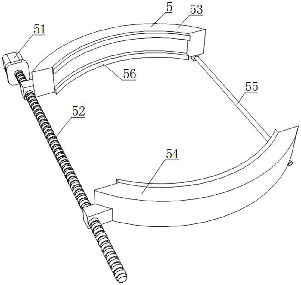
[0033] like Figure 1-6 As shown, on the basis of Embodiment 1, the present invention provides a technical solution: preferably, the positioning mechanism 5 includes a motor 51 and a threaded rod 52, the front of the motor 51 is fixedly connected to the back of the console 4, and the The output shaft is fixedly connected with one end of the threaded rod 52, and the other end of the threaded rod 52 is rotatably connected with the inner wall of the console 4. The outer surface of the threaded rod 52 is threadedly sleeved with a clamp seat 1 53 and a clamp seat 2 54. The clamp seat 1 53. The inside of the second clamp seat 54 is respectively provided with a positive thread and a reverse thread that are adapted to the outer surface of the threaded rod 52, and the inner arc surfaces of the first clamp seat 53 and the second clamp seat 54 are fixedly connected with soft extrusion bushings 56. The inner wall of the bottom surface of one end of the clamp seat 53 and the clamp seat 2 5...

Embodiment 3

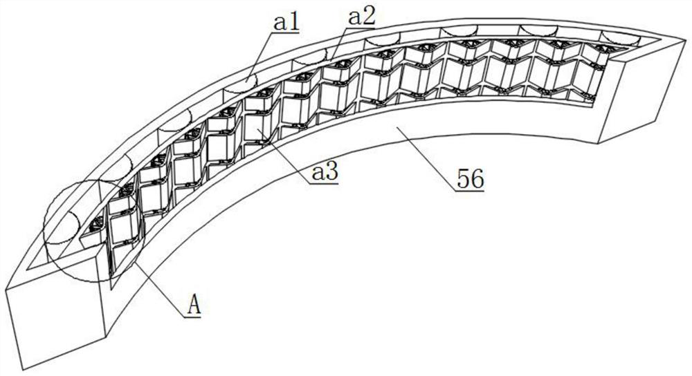
[0035] like Figure 1-6 As shown, on the basis of Embodiment 1, the present invention provides a technical solution: preferably, micro-elastic rubber pads a1 are fixedly installed on the inner surface of the soft extrusion sleeve 56, and the micro-elastic rubber pads a1 are equally spaced. On the inner surface of the soft extrusion sleeve pad 56, the outer surface of the micro-elastic rubber pad a1 is fixedly connected with a soft curved surface pressure plate a2, and the two ends of the soft curved surface pressure plate a2 are connected with the soft extrusion sleeve cushion 56. The inner surface is fixedly connected, an elastic flap a3 is fixedly installed on the outer surface of the soft arc pressure plate a2, the outer surface of the elastic flap a3 is fixedly connected with the inner surface of the soft extrusion sleeve 56, and the inner side of the elastic flap a3 is fixedly connected. The surface is fixedly connected with an elastic limiting aligning plate a5, one end ...


PUM


Abstract

The invention discloses a numerical control machine tool with a material guide channel, and relates to the technical field of numerical control machine tools, the numerical control machine tool comprises a numerical control machine tool body, the numerical control machine tool body is composed of a control device, a polishing mechanism and an operation table, and the bottom end of the right side of the control device is connected with the left side of the operation table in a welding mode; the grinding mechanism is arranged above the operation table, a positioning mechanism is arranged on the upper surface of the operation table, a material guide channel is welded to the right side of the operation table, and a bearing mechanism is fixedly installed on the right side of the material guide channel and comprises a material receiving box and a bearing pressure relief assembly. Through the cooperation of stretching and retracting of the hydraulic device and the ejector plate, a machined workpiece is pushed to move, rapid conveying and guiding of the workpiece are assisted through inclination of the guide channel and rotation of the guide sliding roller, buffering is conducted in cooperation with the bearing pressure relief assembly, and therefore stable conveying of the workpiece is guaranteed, and workpiece abrasion caused by collision is prevented.

Description

technical field [0001] The invention relates to the technical field of numerical control machine tools, in particular to a numerical control machine tool with a material guide. Background technique [0002] A CNC machine tool is an automatic machine tool equipped with a program control system. The control system can logically process the program specified by the control code or other symbolic instructions, decode it, represent it with coded numbers, and enter the CNC through the information carrier. device. After operation processing, various control signals are sent by the numerical control device to control the action of the machine tool, and the parts are automatically processed according to the shape and size required by the drawing. The inspection is returned to the warehouse, and when the material is guided, due to the inclined setting of the material guide, the workpiece is prone to collision and wear, and the workpiece blank is not easy to locate during processing. ...

Claims


Application Information

Patent Timeline
Patent Type & Authority Applications(China)
IPC IPC(8): B24B19/00B24B41/00B24B41/02B24B41/06B24B47/00B24B55/00
CPCB24B19/00B24B41/06B24B47/00B24B41/005B24B41/02B24B55/00Y02P90/02
Inventor 张凯
Owner 张凯
Why Eureka
Try Eureka