Mini double-optical-filter switcher with small lens

A dual-filter, mini-type technology, applied in the directions of instruments, optics, camera bodies, etc., can solve the problems of complex process, affecting product verticality, high labor and material costs, simplifying the process and reducing short circuits. Poor, the effect of simplifying the assembly process

Inactive Publication Date: 2022-08-05
东莞市臻荣电子有限公司
View PDF0 Cites 0 Cited by
  • Summary
  • Abstract
  • Description
  • Claims
  • Application Information

AI Technical Summary

Problems solved by technology

[0002] The optical filter is an optical device used to select the required radiation band. The traditional double filter switching device has a relatively complicated process, high manpower and material costs, and at the same time, it is easy to affect the product when the screw part of the cover is connected to the base. The verticality after assembly, etc., so a miniature double filter switcher with a small lens is designed here to solve the above problems

Method used


Image

  • Mini double-optical-filter switcher with small lens

Examples


Embodiment 1

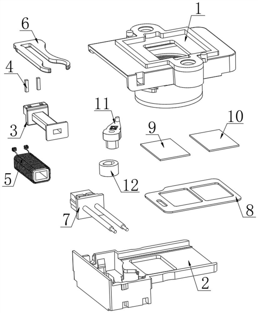
[0014] see figure 1 , this embodiment provides a mini-type dual filter switcher with small lens, including a face cover 1 and a bottom case 2, the face cover 1 and the bottom case 2 are detachable and connected, and the bottom of the inner wall of the bottom case 2 is provided with a wire frame 3, and the wire Pins 4 are arranged in the slots on both sides of the top of one end of the rack 3, and each pin 4 is inserted into the slot of the wire rack 3. A coil 5 is wound around the middle of the wire rack 3, and both ends of the coil 5 are respectively connected with the two sockets. Needle 4 is welded, a U-shaped iron 6 is provided on the side of the wire rack 3 away from the bottom case 2, the straight end of the U-shaped iron 6 is inserted into the square hole in the middle of the wire rack 3, and a terminal wire 7 is provided on the top of the wire rack 3 away from the bottom case 2. , the two ends of the terminal wire 7 are respectively welded with two pins 4, a magnet 12 ...

Embodiment 2

[0018] see figure 1 , on the basis of Embodiment 1, further improvements have been made: the contact surface of the crank handle 11 and the magnet 12 is fixed by dispensing connection, the face cover 1 and the bottom case 2 are fixed by plugging and buttoning, and the hook on the top of the crank handle 11 penetrates the microphone The sliding groove at the end of the pull tab 8 is slidably connected to it, and the crank handle 11 and the magnet 12 are connected and fixed by dispensing glue, which not only effectively improves the stability of the installation and connection, but also effectively guarantees the installation and connection. Convenience, avoiding the complicated steps of the traditional connection method and affecting the installation efficiency. Through the sliding connection between the crank handle 11 and the Mylar sheet 8, when the coil 5 generates a magnetic field, when the magnet 12 drives it to swing left and right, Drive the Mylar 8 to form a pull switch...


PUM


Abstract

The invention discloses a mini dual-optical-filter switcher with a small lens, and relates to the technical field of optical filter switching, the mini dual-optical-filter switcher comprises a surface cover and a bottom shell, the surface cover is detachably connected with the bottom shell, a coil holder is arranged at the bottom of the inner wall of the bottom shell, pins are arranged in slots at two sides of the top of one end of the coil holder, and each pin is inserted into the slot of the coil holder. The two ends of the coil are welded to the two contact pins respectively, U-shaped iron is arranged on the side, away from the bottom shell, of the coil holder, and the linear end of the U-shaped iron is connected with a square hole in the middle of the coil holder in an inserted mode. According to the invention, the technological process is effectively simplified, and the manpower and material cost is reduced; the assembly process is simplified; the circuit of the switcher is sealed in the internal space, so that short circuit caused by contact with the outside is reduced, and the problem of poor open circuit caused by scratching and pulling can be effectively avoided; the thread part of the surface cover and the base are integrated, so that the perpendicularity of a product during assembly is ensured; and meanwhile, the light leakage phenomenon caused by product assembly gaps can be effectively avoided.

Description

technical field [0001] The invention relates to the technical field of filter switching, in particular to a miniature dual-filter switcher with small lenses. Background technique [0002] The filter is an optical device used to select the desired radiation band. The traditional dual-filter switching device has a complicated process, high labor and material costs, and the screw part of the cover is easy to affect the product when it is connected to the base. Due to the verticality after assembly, a mini-type dual filter switcher with small lens is designed here to solve the above problems. SUMMARY OF THE INVENTION [0003] The purpose of the present invention is to provide a miniature dual-filter switcher with small lens to solve the above-mentioned problems in the background art. [0004] In order to achieve the above purpose, the present invention provides the following technical solutions: a miniature dual-filter switcher with small lenses, comprising a face cover and a...

Claims


Application Information

Patent Timeline
Patent Type & Authority Applications(China)
IPC IPC(8): G03B17/14
CPCG03B17/14
Inventor 林子平吴鑫
Owner 东莞市臻荣电子有限公司
Why Eureka
Try Eureka