PLC-based dewatering and drainage intelligent control system and method

A technology of intelligent control system and control method, which is applied in the direction of comprehensive factory control, electrical program control, program control in sequence/logic controllers, etc. Strong performance, high efficiency, and the effect of human-computer interaction and data feedback

Active Publication Date: 2022-08-05
CHINA CONSTR IND & ENERGY ENG GRP CO LTD
View PDF8 Cites 0 Cited by
  • Summary
  • Abstract
  • Description
  • Claims
  • Application Information

AI Technical Summary

Problems solved by technology

Most of the current foundation pit construction projects adopt the method of dewatering with open trenches and water collection wells. In the process of material preparation, the number, power and type of water pumps selected should meet the requirements to ensure that the total displacement is 1.5~ 2 times; therefore, in some large-scale projects, at least forty or fifty water pumps need to be used for foundation pit drainage. The number of water pumps used is large, the total value is high, energy consumption is large, and construction costs are high
[0003] In addition, the traditional drainage management method for foundation pits is to set up full-time personnel to monitor the groundwater level and the operation status of pumping equipment for 24 hours. Information such as the rate of water level drop and drainage time can only be roughly recorded and counted through paper documents, which is not accurate. If the monitoring is not timely and the precipitation is stopped halfway, it will cause the groundwater level to rise, leading to safety accidents such as flooding of buildings in the foundation pit and landslides of earthwork slopes, and will also affect the construction period and cause immeasurable losses

Method used


Image

  • PLC-based dewatering and drainage intelligent control system and method
  • PLC-based dewatering and drainage intelligent control system and method
  • PLC-based dewatering and drainage intelligent control system and method

Examples


Embodiment Construction

[0041] The present invention will be further described below with reference to the accompanying drawings and specific embodiments, but the protection scope of the present invention is not limited thereto.

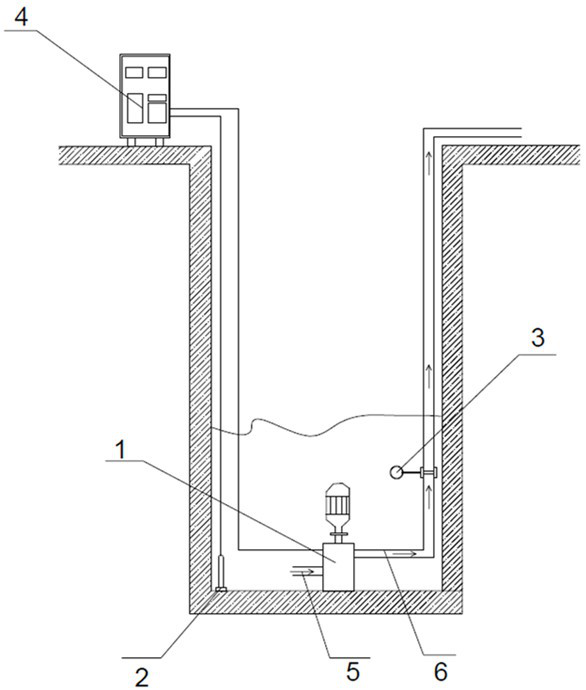
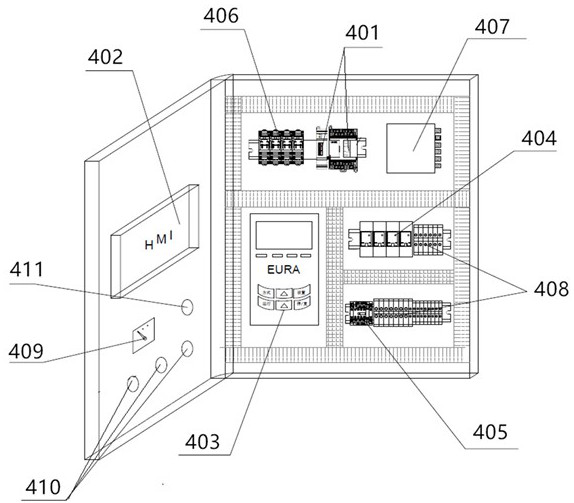
[0042] In the description of the present invention, it should be understood that the terms "installation", "connection", "fixation", etc. should be understood in a broad sense, for example, it may be a fixed connection, a detachable connection, or an integral connection, and It is a direct connection, an indirect connection through an intermediate medium, or an internal connection between two components. image 3 , 4 The combination of English letters, English letters and numbers in Chinese represents the corresponding electrical symbols or terminals, which are common knowledge in the field, and will not be repeated in the present invention. For those of ordinary skill in the art, they can situation to understand the specific meanings of the above terms in the present inve...


PUM


Abstract

The invention provides a PLC-based dewatering and drainage intelligent control system and method. The PLC-based dewatering and drainage intelligent control system comprises a liquid level meter, a flow meter, dewatering and drainage equipment and a control cabinet, and the control cabinet takes a touch screen and a PLC as the core. The PLC reads liquid level change data in the water collecting well in real time through the liquid level meter to serve as a calculation basis of the water inflow in the control system, and parameterization control over dewatering and drainage equipment in a manual mode and an automatic mode is achieved in combination with setting of an efficient operation section in a characteristic curve. And the PLC controls the working state of the dewatering and drainage equipment by using the corresponding high-efficiency frequency and flow control data set under different lifts manually input in the touch screen parameter setting interface, so that the high-efficiency operation of the dewatering and drainage equipment is ensured, and the realization of energy conservation and consumption reduction is facilitated. In addition, man-machine interaction and data feedback can be achieved, operators can conveniently know the water level working condition in the collecting well and the running state of dewatering and drainage equipment in real time, and then the corresponding running mode is selected to achieve efficient dewatering and drainage.

Description

technical field [0001] The invention belongs to the technical field of dewatering and drainage intelligent control, and in particular relates to a PLC-based dewatering and drainage intelligent control system and method. Background technique [0002] At present, large-scale public buildings and housing constructions are mainly high-rise buildings. The project volume is large and the depth of the foundation pit is also deep, which promotes the rapid development of deep foundation pit engineering. The construction requirements of deep foundation pit projects are relatively strict. As an important part of foundation pit engineering construction, foundation pit drainage and drainage are directly related to the quality of construction projects. At present, most of the foundation pit construction projects adopt the method of open ditch and water collection well for dewatering. In the process of material preparation, the number, power and model of the selected water pumps should mee...

Claims


Application Information

Patent Timeline
Patent Type & Authority Applications(China)
IPC IPC(8): G05B19/05
CPCG05B19/054G05B2219/1109Y02P90/02
Inventor 孙梓尧姚盛清王奇张艳芳高增孝肖智中金树楼项龙康张睿
Owner CHINA CONSTR IND & ENERGY ENG GRP CO LTD
Why Eureka
Try Eureka