Low-delay audio signal overdetermined blind source separation method and separation device

A technology for audio signal and blind source separation, applied in speech analysis, instruments, etc., can solve the problem that the system delay cannot be significantly reduced

Active Publication Date: 2022-08-05
INST OF ACOUSTICS CHINESE ACAD OF SCI
View PDF6 Cites 0 Cited by
  • Summary
  • Abstract
  • Description
  • Claims
  • Application Information

AI Technical Summary

Problems solved by technology

The current real-time blind source separation algorithm cannot significantly reduce the system delay

Method used


Image

  • Low-delay audio signal overdetermined blind source separation method and separation device
  • Low-delay audio signal overdetermined blind source separation method and separation device
  • Low-delay audio signal overdetermined blind source separation method and separation device

Examples


Embodiment 1

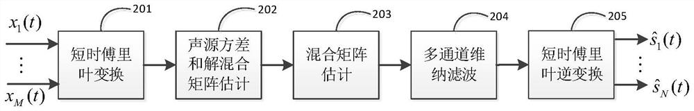
[0077] figure 2 It is a system block diagram of the real-time blind separation method of audio signal according to the present invention, the method includes short-time Fourier transform 201, sound source variance and demixing matrix calculation 202, mixing matrix estimation module 203, multi-channel Wiener filtering 204 and short-time Fourier transform Inverse Liye Transform 205.

[0078] The present invention provides a low-latency audio signal overdetermined blind source separation method, which includes:

[0079] Short Time Fourier Transform 201

[0080] Perform short-time Fourier transform on each time-domain signal of each to-be-separated sound source in the target environment collected by the microphone array to obtain a corresponding current frame time-frequency domain observation signal; specifically, the short-time Fourier transform Transform 201 respectively to the signal x received by the microphone element m (t) Perform short-time Fourier transform to get X m...

Embodiment 2

[0133] like Figure 4 As shown, the present invention also provides a low-latency audio signal overdetermined blind source separation device, the device comprising:

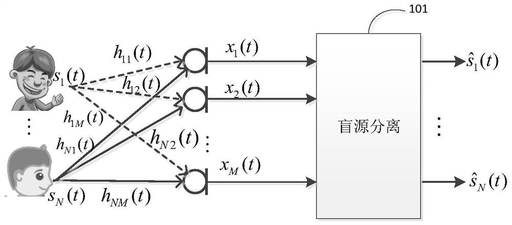
[0134] The microphone array 401 includes M microphone array elements, which are used to pick up the acoustic signals of N sound sources to be separated in the target environment, and the total number of microphone array elements is required to be greater than the number of sound sources to be separated, that is, M>N; M≥3 ; N≥2;

[0135] The A / D module 402 is configured to convert the acoustic signals (analog signals) of the N sound sources to be separated picked up by the microphone array 401 into corresponding digital signals, so as to be sent to the processor and other devices to execute the relevant separation algorithm ; In the MEMS microphone, the A / D module 402 can be integrated in the microphone.

[0136] The short-time Fourier transform module 403 is used for buffering the signals collected by the micro...


PUM


Abstract

The invention belongs to the technical field of frequency domain blind source separation and audio signal processing, and particularly relates to a low-delay audio signal overdetermined blind source separation method, which comprises the following steps that: each microphone array element in a microphone array picks up sound signals of N sound sources to be separated in a target environment and converts the sound signals into corresponding digital signals, performing short-time Fourier transform on the time-frequency domain observation signal to obtain a corresponding time-frequency domain observation signal; repeatedly iterating and updating the obtained time-frequency domain observation signals until convergence is achieved, and obtaining the variance and the de-mixing vector of each sound source to be separated; constructing a de-mixing matrix by using the obtained de-mixing vector; performing inversion on the de-mixing matrix to obtain estimation of a mixing matrix; for each to-be-separated sound source, based on the hybrid matrix, constructing a multi-channel Wiener filter and performing filtering to obtain a time-frequency domain to-be-separated signal; and performing short-time inverse Fourier transform to obtain the time domain waveform of the signal to be separated.

Description

technical field [0001] The invention belongs to the technical field of frequency domain blind source separation (BSS) and audio signal processing, and in particular, relates to a method and a separation device for overdetermined blind source separation of low-latency audio signals. Background technique [0002] In the scene of multiple speakers speaking at the same time, people can focus on the voice of one interested speaker and automatically ignore the voices of other speakers, which is the famous "cocktail party" problem. This question was first proposed by British cognitive scientist Professor Cherry in the 1950s. However, this question has remained unresolved for a long time. Blind source separation is a new field developed to solve this problem. Blind source separation of audio signals has broad application prospects, including human-computer voice interaction, automatic meeting logs, and music separation. [0003] In the past two decades, frequency-domain blind sou...

Claims


Application Information

Patent Timeline
Patent Type & Authority Applications(China)
IPC IPC(8): G10L21/0272G10L21/0208
CPCG10L21/0272G10L21/0208G10L2021/02082Y02D30/70
Inventor 王泰辉
Owner INST OF ACOUSTICS CHINESE ACAD OF SCI
Why Eureka
Try Eureka