
Arm infusion port protection device

A protection device and infusion port technology, applied in the direction of instruments and needles introduced into the body, can solve the problems of inconvenient operation, inconvenient operation, puncture membrane damage, etc., and achieve the effect of no safety hazard, convenient operation, and stable clamping and positioning

Inactive Publication Date: 2022-08-09
CHONGQING UNIV CANCER HOSPITAL
View PDF0 Cites 1 Cited by
  • Summary
  • Abstract
  • Description
  • Claims
  • Application Information

AI Technical Summary

Problems solved by technology

Because the patient has used the infusion port for a long time, if the infusion port is not protected, the surface of the infusion port may be wet and easy to cause infection due to the patient’s bathing; It is inconvenient, and when the needle is punctured, the puncture position can only be found through the naked eye of the medical staff. If the light is dark, the operation is extremely inconvenient. If the puncture position is slightly deviated, it may cause damage to the puncture membrane

Method used


Image

  • Arm infusion port protection device
  • Arm infusion port protection device
  • Arm infusion port protection device

Examples


Embodiment 1

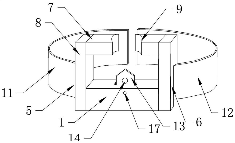
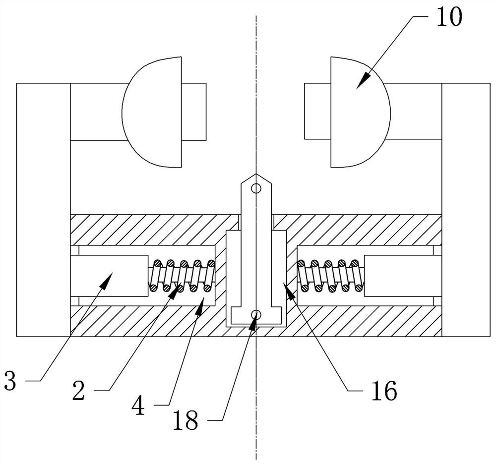
[0025] Instructions attached figure 1 , attached figure 2 Reference numerals in include: connecting plate 1, tension spring 2, guide column 3, groove 4, left top plate 5, right top plate 6, clamping section 7, bending section 8, concave curved surface 9, infusion port semi-protection The cover 10 , the first elastic band 11 , the second elastic band 12 , the guide piece 13 , the guide hole 14 , the installation groove 15 , the T-shaped end 16 , the second positioning hole 17 , and the first positioning hole 18 .

[0026] as attached figure 1 and attached figure 2 Shown: the arm infusion port protection device described in this embodiment includes a connecting plate 1, a left top plate 5, a right top plate 6, an infusion port half protective cover 10, a first elastic band 11, a second elastic band 12, and a guide post 3 and guide plate 13.

[0027] The left top plate 5 and the right top plate 6 are both L-shaped and arranged in mirror images. Both the left top plate 5 and...

Embodiment 2

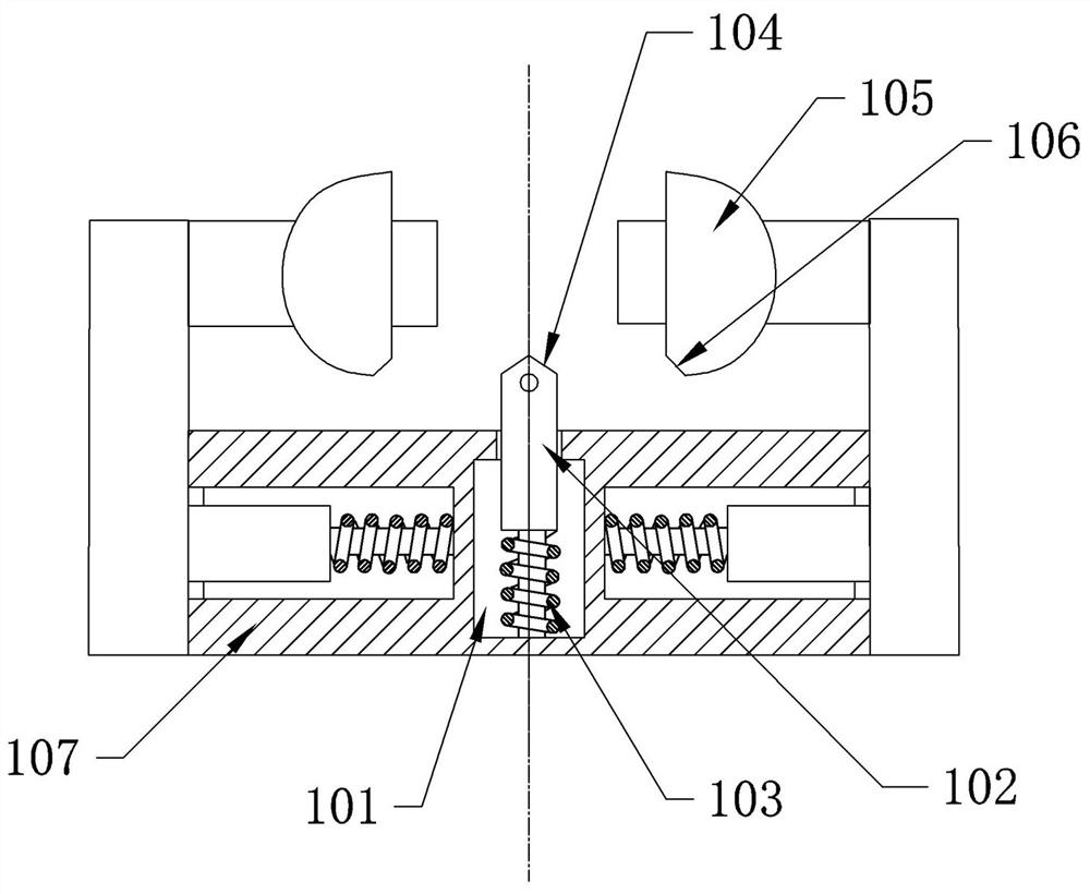
[0033] as attached figure 2 As shown, the reference numerals include an installation groove 101 , a guide piece 102 , a compression spring 103 , a conical surface 104 , a half protective cover of the infusion port 105 , an inclined surface 106 , and a connecting plate 107 .

[0034] The difference between this embodiment and the first embodiment is that the installation manner of the guide piece 102 is different.

[0035]In this embodiment, a compression spring 103 is provided between the groove bottom of the installation groove 101 and the lower end of the guide piece 102. When the pressure spring 103 is in an uncompressed natural state, the guide piece 102 is just at the puncture position of the infusion port, and the guide hole The position is directly opposite to the puncture position. In this embodiment, the upper end surface of the guide piece 102 is a smooth curved surface or a tapered surface 104 , which is preferably a tapered surface 104 in this embodiment. holdin...


PUM


Abstract

The invention relates to the technical field of infusion protection devices, in particular to an arm infusion port protection device which comprises a left top plate and a right top plate which can move relatively and are used for clamping an infusion port, the left top plate and the right top plate are both in an L shape and are arranged in a mirror image mode, and each of the left top plate and the right top plate comprises a clamping section and a bending section. The portion between the two clamping sections is used for clamping and positioning an infusion port, each clamping section is provided with an infusion port half protection cover capable of moving along the clamping section, the end face of one infusion port half protection cover is provided with a metal strip, and the end face of the other infusion port half protection cover is provided with a strip-shaped magnet. The two infusion port semi-protection covers are buckled and cover the infusion port by attracting the metal strips through the magnets. The arm infusion port protection device not only can protect an infusion port, but also can position the infusion port during puncture.

Description

technical field [0001] The invention relates to the technical field of infusion protection devices, in particular to an arm infusion port protection device. Background technique [0002] The infusion port is also called the venous infusion port, which is the abbreviation of the fully implanted central venous catheter system or the fully embedded drug infusion device. It is mainly composed of an injection seat for puncture and an intravenous catheter, which can provide a safe, convenient and long-term portable vascular channel for patients who have long-term infusion of chemotherapy drugs, blood transfusion and blood sample collection, long-term parenteral nutrition, and long-term infusion of chronic diseases. Since the patient has used the infusion port for a long time, if the infusion port is not protected, the surface of the infusion port may become wet and easy to cause infection due to the patient's bathing. It is inconvenient, and when the needle is punctured, the punc...

Claims


Application Information

Patent Timeline
Patent Type & Authority Applications(China)
IPC IPC(8): A61M5/158
CPCA61M5/158
Inventor 肖静
Owner CHONGQING UNIV CANCER HOSPITAL
Learn More